Announcement

Collapse
No announcement yet.

Triangular Wave Technology

Collapse
X
 
  • Filter
  • Time
  • Show
Clear All
new posts

  • #76
    Hi guys,

    sorry for missing heaps of infos. But it was intended to show you the rough netto response comprison. Anyway. Here is more info:
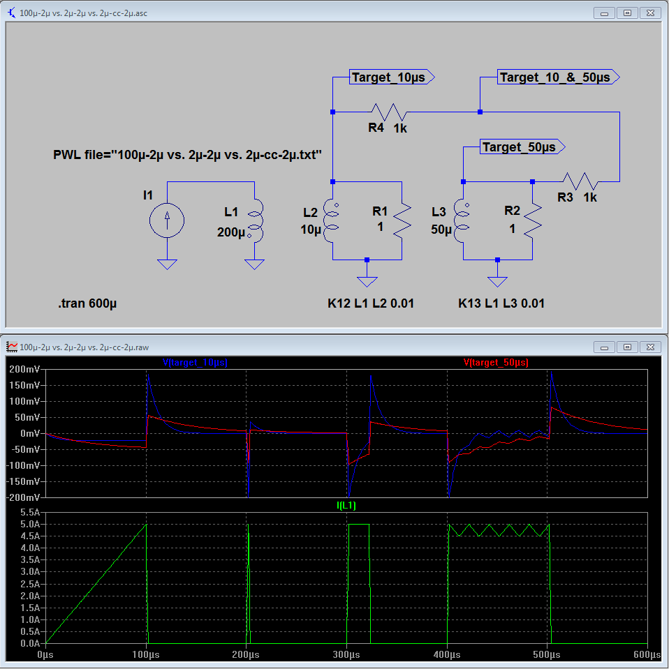
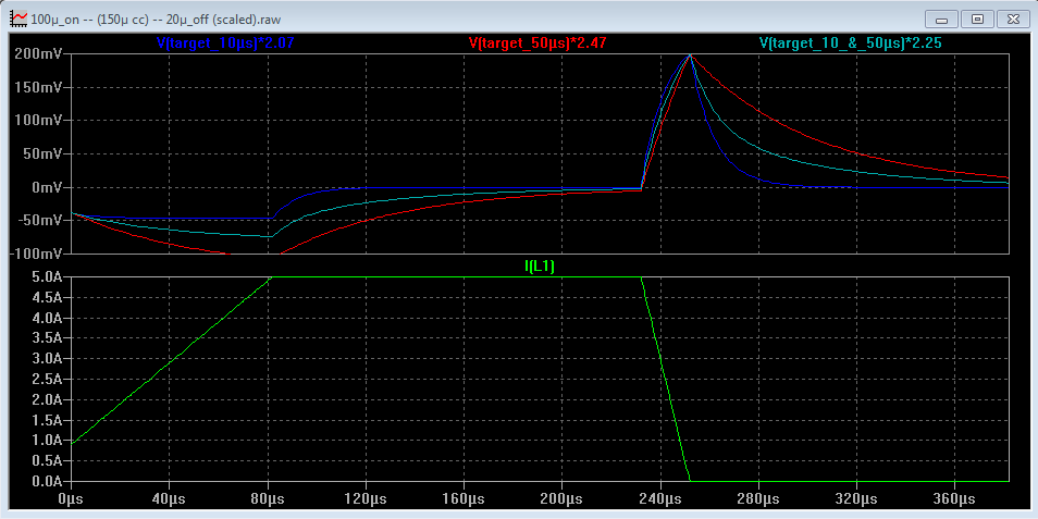
    PPS = 3000, L=600µH, Lr=0.2 Ohm, target TC 1 ms very weak coupled (k=0.001)
    Sampling on a PI begins at 50 mV at the decay voltage of the reference PI configuration. The reference PI configuration is an independent and exact copy of the PI configuration and there isn't any target coupled to it. The difference of the PI and reference PI is taken into account for the comparison. No pulse on response taken into account on a PI. And no amplifier present on all configurations. Same coils and targets presented to all configurations.

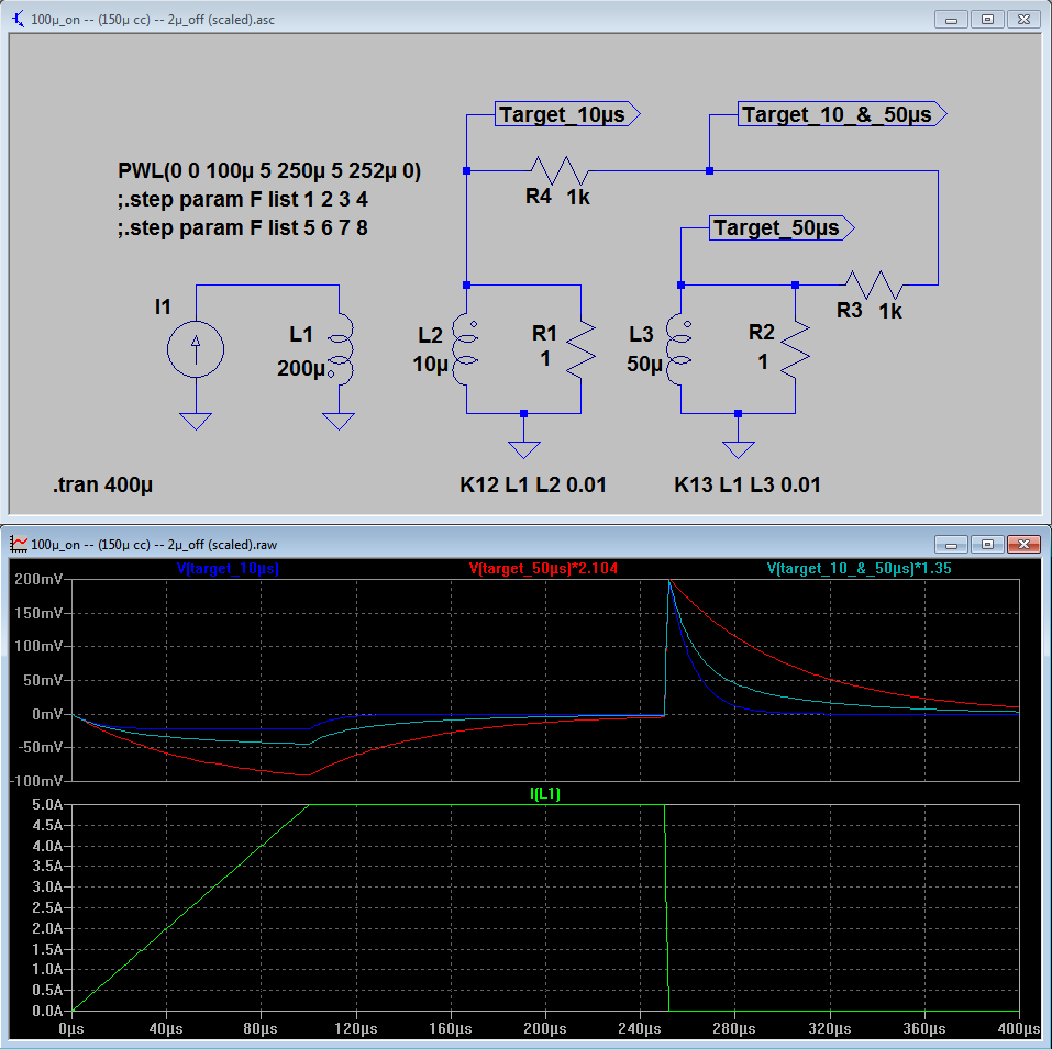
    The crucial point is, that other configurations can make use of the pulse-on response too. That's the reason, why the PI configuration response goes towards to zilch compared to the other configurations.

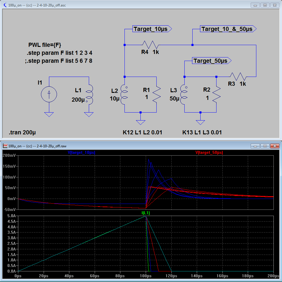
    If you make a spice comparison of all configurations, you can see the huge difference in response.
    I've finished with PI's. *LOL*
    Cheers,
    Aziz

    Comment


    • #77
      BTW guys,

      the new X-named configuration is more power efficient than the TEM configuration and it delivers 3-4 times more target response.
      But you would need a complex circuit to process the response. All gets very easy in the frequency domain using DSP platforms however.

      I'm onto the way to develop the "Giant Nugget Detector" or the "Whopper Nugget Detector". *LOL*
      Aziz

      Comment


      • #78
        Hi,

        there still seems to be some confusion and different opinions on what actually kicks the target in PI detectors, and how the duration of the pulses affects the target’s response. We already discussed this on the PI Technology Forum 11 years ago. Dave Johnson posted many detailed explanations, and I also added some of my own experience.

        In a conventional PI it is the flyback pulse that produces usable eddy currents in the target. The eddy currents produced by the driving pulse are counterproductive.

        You can still find these old posts on Eric’s PI Technology Forum, like these from Dave:
        http://www.findmall.com/read.php?34,129490
        http://www.findmall.com/read.php?34,129532
        http://www.findmall.com/read.php?34,129541

        Or from me:
        http://www.findmall.com/read.php?34,129572
        http://www.findmall.com/read.php?34,129617
        http://www.findmall.com/read.php?34,...653#msg-129653

        Originally posted by Ferric Toes View Post
        PRO FLYBACK. Are you saying that if you pulsed a coil with, say, just a 2uS 500V pulse, then that is a good as a long low voltage (100uS or more) conventional pulse that generates a 2uS 500V flyback anyway?
        If the 2µs/500V driving pulse is placed immediately before the flyback pulse, then the answer is no. But if you add a constant current phase in between these two, then the target’s response will be the same or even better, depending on the length of the constant current phase and the time constant of the target.

        As described on the PI Technology Forum, the constant current phase can be created by either using a second low voltage power supply with a linear current regulation, or by using a chopping controlled current drive. Both methods will of course increase the power loss, but also the target response, especially for targets with longer TCs.

        Below is a simulation with a 200µH TX coil and two targets, one with a TC of 10µs and one with 50µs. Peak current is 5A. From left to right:

        (A) 100µs/10V driving pulse, 2µs/500V flyback pulse
        (B) 2µs/500V driving pulse, 2µs/500V flyback pulse
        (C) 2µs/500V driving pulse, 20µs constant current (5A), 2µs/500V flyback pulse
        (D) 2µs/500V driving pulse, 100µs constant current (chopped, mean value 4.75A), 2µs/500V flyback pulse


        Results:
        (B) Produces a very weak response for both targets, much lower than (A)
        (C) The response of the 10µs target is already better than (A)
        (D) Both targets have a higher response than (A), especially the one with the longer TC

        Any eddy currents caused by the driving pulse that are still present in the target at the time when the flyback pulse starts will reduce the response. Provided that driving pulse and flyback pulse are time separated by several target TCs, the amplitude of the target’s response after the flyback pulse depends on the following two factors:

        1. It is proportional to the square root of the TX coil’s energy for a given flyback pulse length.
        To double the amplitude of the response, 4 times of coil energy is needed.

        2. It depends on the ratio of target time constant to flyback pulse length.
        The maximum target response for a given coil energy occurs when the flyback pulse is as short as possible (highest dI/dt). In practice, this is limited by the highest possible flyback voltage and the smallest feasible coil inductance, but in the simulation the duration can be set to nanoseconds with megavolts of flyback voltage. Let’s assume this represents 100% of the possible target response. Then a flyback pulse length that has exactly one target TC results in an amplitude of 63.2%. At 0.5TC it is 78.7%, at 0.2TC 90.7%, and at 0.1TC it reaches 95.2%. Here is a table with values from a simulation. First column is the length of the flyback pulse in multiples of target TCs, second column the relative amplitude.

        FB length
        (TC times)
        %
        0.0001 100
        0.1 95.17
        0.2 90.66
        0.5 78.72
        1 63.24
        2 43.25
        4 24.55
        8 12.50
        16 6.25
        32 3.12
        64 1.56
        The 63.24 % value at 1 TC is very close to the 1 TC value of the well known exponential charging/discharging responses of inductors. Maybe someone can have a closer look to derive the function of the relationship between the amplitude and the ratio of target TC to flyback pulse length.

        So it is important to note that targets with long TCs do not need long pulses – like targets with shorter TCs, their response gets better the shorter the pulses are. In a conventional PI, however, there are usually residual eddy currents from the driving pulse when the flyback pulse starts. This reduces the target response by exactly the negative response that is present at this time. So longer and/or current limited (flat top) driving pulses found in a conventional PI will increase the response of these targets.

        It is also obvious that it is usually not necessary to have flyback pulses shorter than 2µs – this already yields 91% of the possible amplitude of targets with TCs equal to or higher than 10µs. Even a small gold nugget (let’s assume one with 2µs TC) responds with 63% of the maximum possible value, or 79% if the pulse is shortened to 1µs.

        Below are two simulations that show the response of the two targets for flyback pulse lengths of 2, 4, 10, and 20µs. The first one without a constant current phase:


        And the second one with a constant current phase of 150µs (note that the .tran time is longer):


        - The increase of the response of the target with the 50µs TC is quite small, especially without the cc phase.
        - The increase of the response of the target with the 10µs TC is significant when the flyback pulse is shortened from 20 to 4µs, but quite small from 4 to 2µs (as expected from the table above).


        Shape of the response curve
        For targets with exactly one TC, the shape of the response curve does not depend on the length of the driving and flyback pulses. For targets with more than one TC, the shape will of course change. If the driving pulse is immediately followed by the flyback pulse (like in conventional PIs), the length of the driving pulse will also affect the shape, otherwise it is only the flyback pulse length.

        The following 2 simulations show the influence of the flyback pulse length on the shape of the response curve of a target with 2 TCs of 10 and 50µs. Note that I scaled the different curves so that the maximum is 200mV in all plots. This reveals the difference of the shape.

        First one with 2µs flyback pulse:


        Second one with 20µs flyback pulse:


        As expected, the two curves for both the 10µs and 50µs targets are unchanged, but the curve for the combined TCs has changed (less short TC components). Real objects usually have more than two TCs, but I guess only a few are dominant. It would be interesting to find out if and how the magnetic and electric coupling in real targets affects the sum of the individual TCs.

        For those who would like to play with the simulations, here is a RAR archive:
        http://www.tb-electronic.de/pi_tech/CC1.rar

        Happy simulating!
        Thomas

        Comment


        • #79
          Originally posted by Aziz View Post
          I've finished with PI's. *LOL*
          And I'm constantly struggling to even get my feet wet with PI. Intuitively I known the moment I entered this hobby that step voltage is the way to go. There is also a lot to re-do with CW VLF.

          Comment


          • #80
            Thanks for posting the well explained simulations. I remember the discussion on the PI classroom. I perfectly agree with your theory, but............

            This flattop is good for reducing the TX eddy currents to 0. At a great expense of power and time.
            50us TC targets are small targets. Silver coins can have a TC of several hundred us. Giant nuggets (that are really worth searching for) have a TC of 1000us.

            Limiting the TX current, limits the peak current without reducing power consumption.

            I see no other advantage in this method, than reducing the TX eddy currents at the time of switch OFF.

            Our TEM method is much more effective. It did not exist yet, years back, for the great discussion and is little understood yet today, but you might have a look at it and find it interesting.

            Tinkerer

            Comment


            • #81
              Gee!, I didn't see the new post and was wondering, why Tinkerer is mentioning the simulation pics. And then, I saw it finally. BTW, great post Thomas. Thank you for your contribution and effort.

              But it doesn't help much. I'm absolute totally totally finished with PI's.
              And there is a very very good reason for.

              PI is dead. Long live the PI.


              Cheers,
              Aziz

              Comment


              • #82
                Originally posted by PiTec View Post
                (B) 2µs/500V driving pulse, 2µs/500V flyback pulse
                Hi Thomas, You've been busy in meantime
                I think you missed one simple option here, a voltage drive. A short voltage will energise a Tx coil in exactly the same way as flyback would, yet after the pulse is removed you will have continuation of current according to the very tau of the coil and perhaps some electronic parts on it's way. If you apply the next short voltage pulse of the same span, but opposite polarity, you will in effect gain a situation explained in (C), which is quite useful.
                I'm just emphasizing this case because this one is perhaps the easiest of all to solve by garden variety electronics, and yet very effective.

                Welcome to this forum

                Comment


                • #83
                  BTW guys,

                  don't look at the induced current in a target. Look what comes back to the receive coil.
                  Aziz

                  Comment


                  • #84
                    Tinkerer, I just wanted to explain what is causing the target response, and how the pulse lengths and the pulse sequence affects the amplitudes in a conventional PI.

                    Of course the TEM method is better in terms of efficiency. However, don’t forget that it is possible to recover a good portion of the energy in a conventional PI. This could be 75% or more if the coil has a low DC resistance and the cc phase is not too long or not present. Also, there are a lot of applications where only mono coils can be used.


                    Originally posted by Davor View Post
                    I think you missed one simple option here, a voltage drive.
                    I don’t see your point … there are short pulses of 2µs/500V/5A, but only the current is plotted.


                    Originally posted by Aziz View Post
                    don't look at the induced current in a target. Look what comes back to the receive coil.
                    We have essentially the same curves at the RX coil regarding shape and relative amplitude, but with a TX voltage offset. So for explaining the target response, the pure target eddy currents are more suitable. Here’s a simulation showing identical curves for the RX voltage V(rx) and the target eddy current V(target_10µs) with some V(tx) offset added:

                    Click image for larger version

Name:	test.png
Views:	1
Size:	45.7 KB
ID:	334730

                    Thomas

                    Comment


                    • #85
                      Originally posted by PiTec View Post
                      We have essentially the same curves at the RX coil regarding shape and relative amplitude, but with a TX voltage offset. So for explaining the target response, the pure target eddy currents are more suitable. Here’s a simulation showing identical curves for the RX voltage V(rx) and the target eddy current V(target_10µs) with some V(tx) offset added:
                      Hi Thomas,

                      Well, I don't agree with you. Just use a separate coupled RX coil for the sake of fun and clarity. If you have a mono coil, look at the decay curve (induced voltage on the mono coil), where your target response signal is being possible to be sampled.

                      While we are at it, we could sum up the processable target response on the receive coil and compare it against the sum of maximum possible target response. That is an eye-opener!

                      Cheers,
                      Aziz

                      Comment


                      • #86
                        Originally posted by PiTec View Post
                        I don’t see your point … there are short pulses of 2µs/500V/5A, but only the current is plotted.
                        OK. My point is that supplying a Tx coil with a current source means that you are implying infinite impedance at the Tx coil, as if the cut-off-the-coil-to-produce-flyback PI decorum was on your mind. As I see it now you have it covered.

                        Comment


                        • #87
                          Aziz, remember that my simulation is only to demonstrate how the eddy currents affect the target response in a conventional PI. The voltage offset visible in an RX coil during the on-times is not relevant for this, and the signal decay curve of a mono coil after the flyback pulse has exactly the same shape and relative amplitude as the target eddy current anyway. Of course this is only true for ideal components, in the real world we have some unwanted decay signals from parasitic component properties.

                          Davor, it is much easier to set up a current source with whatever timing sequences you want than using a pulsed voltage source which would require more PWL points, opposite polarities, and calculation of the voltage levels. The simulation results are the same, so I used a current source and an ideal TX coil with no DC resistance.

                          Thomas

                          Comment


                          • #88
                            Originally posted by PiTec View Post
                            Aziz, remember that my simulation is only to demonstrate how the eddy currents affect the target response in a conventional PI. The voltage offset visible in an RX coil during the on-times is not relevant for this, and the signal decay curve of a mono coil after the flyback pulse has exactly the same shape and relative amplitude as the target eddy current anyway. Of course this is only true for ideal components, in the real world we have some unwanted decay signals from parasitic component properties.

                            Davor, it is much easier to set up a current source with whatever timing sequences you want than using a pulsed voltage source which would require more PWL points, opposite polarities, and calculation of the voltage levels. The simulation results are the same, so I used a current source and an ideal TX coil with no DC resistance.

                            Thomas
                            I like your simulations. I like them so much that I want to start a new thread, just about simulations.
                            We can learn a lot with simulations, specially, we can learn to understand the shape of the expected signal wave forms in the metal detectors.

                            One simulation we are having problems with, is the response of a FE target. I believe we can model this with a sum of R and X response, but I have not found a consensus yet.

                            Would you be so kind, to add your knowledge to the Simulation thread?

                            Tinkerer

                            Comment


                            • #89
                              Hi Tinkerer,

                              the simulations that I posted above are rather simple compared to some really complex ones, for example from Aziz.

                              I usually work with real hardware and simulations at the same time. Simulations have their limitations, but they can help and save time while testing different setups. One advantage that I used in the simulations above is that all the unwanted real world effects that usually only obscure the basic principle can be removed easily. And from there we add real world components to see how they affect the results and to find the best design.

                              The response of an FE target is basically not much different to the response of a non-FE target. In an IB setup, some reactive response has to be added as you said, and the response is often much more dependent on the target’s orientation. Maybe I post something it the new thread you’ve opened.

                              Thomas

                              Comment


                              • #90
                                Originally posted by mikebg View Post
                                The next question is:
                                How to distort the sine waveform in order to obtain frequency spectrum like trapezoidal waveform?
                                HINT: See figures of patent mentioned in post #54.
                                This is the answer for question in post # 62:
                                Attached Files

                                Comment

                                Working...
                                X