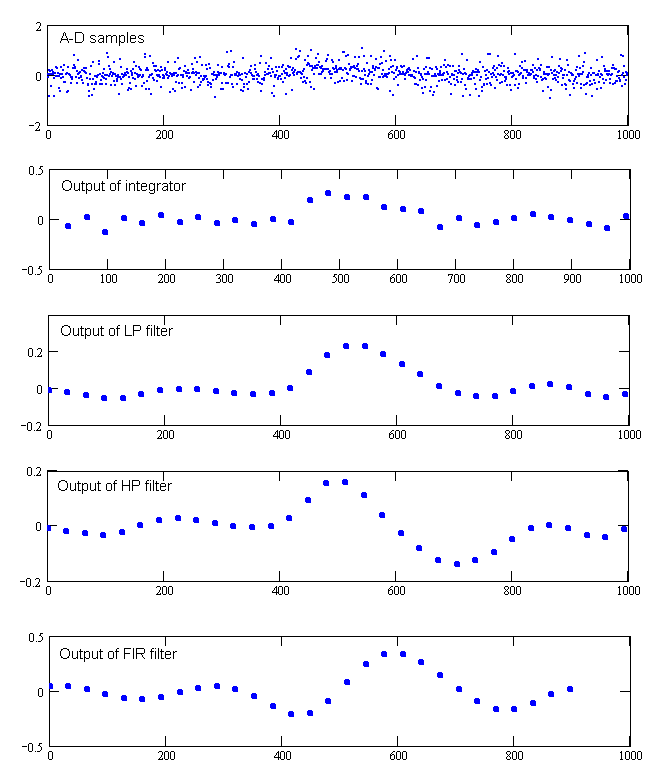
The graphs above are simulations of the signals I am getting at various points in the detector.
The top graph shows 1000 samples of signal and noise. In the simulation this represents one second of data. The detector actually takes 2200 samples per second per channel. The signal is in the area between 400 and 600.
The second graph shows the output of the integrator. In the simulation I am integrating 32 samples. In the detector I integrate 74 samples.
The third graph shows the output of the 2 pole 4.5 Hz low pass filter. At this point the high frequency noise has pretty well been eliminated in the graph. It might look like this is a useable signal and that we are done now. But I did not add any DC component or low frequency ground signal to this simulation. In the detector there would be a large DC component from the ground signal which might be hundreds of times larger than the target signal. So the signal still has to go through another filter to remove the DC and low frequencies.
The fourth graph is the output of the 2 pole 0.85 Hz high pass filter. This removes DC and low frequencies. It also changes the shape of the target signal (it gets differentiated). If there is to be no DC output then whenever the signal goes above 0 for a while it must also go below 0 for a while to balance the DC component. I suspect that this change in signal shape is responsible for some of the incorrect ID's that detectors give. On bottlecaps for example.
The fifth graph is the output of the FIR filter. There was no visible high frequency noise left in the simulation coming into this filter, but there is plenty of noise left in the detector when the target is far enough away. The FIR filter has reshaped the target signal by moving half the dip that followed the peak of the target signal to in front of the signal. There is still the same amount of signal below zero, but now it is evenly split before and after the peak. But it has also delayed the signal. The total delay through all the filters is about .1 second.
Robert
