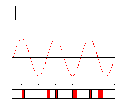
This diagram shows some waveforms and timing.
The top trace represents the coil drive signal from the processor.
Then middle trace represents the resultant voltage developed across the transmit winding.
The bottom section shows a timeline of the interrupts. The shortest interrupts only reset the timer for the next interrupt and to control the drive signal. The other interrupts also read the A/D. The longest interrupts also filter and accumulate the data. This does not show the extra time needed every 60th of a second to low pass filter and store the data. The duration of the interrupts shown here are only approximate.
Robert Hoolko
