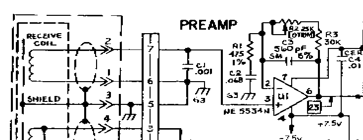
I built a copy of this preamp from the 6000 Di. I did not have any of the right parts, but it does not seem to be too sensitive to component values. I guess it has a wide enough bandwidth that the values are not too critical.
A penny on the coil gives about 300 mV out of the preamp. This is about half of what I wanted, so I will add an op amp behind it later. I will also want more gain if I can get some kind of automatic gain control working. But right now I can already see a penny at 5 inches from the 5.3 coil. That is close to one coil diameter so I am already in the ball park.
FIRST DATA
This is the first set of data from the receive coil.
Air -155, -98
Ferrite 1463, 2846
Foil 346, -425
Penny 268, -2731
Penny at 3" -141 -155
Subtracting the Air values from the others and then calculating the angle I get.
Ferrite 1618, 2944, 61°
Foil 501, -327, -33°
Penny 423, -2633, -81°
Penny at 3" 14, -57, -76°
Where the third number is the angle in degrees. By themselves these angles do not mean anything because nothing has been calibrated. But using ferrite as the reference I get.
Foil = +94°
Penny = +142°
Penny at 3" = +137°
These are the phase angles of these targets relative to a ferrite reference. The approximate numbers that I would expect for these targets are foil +100° and zinc penny +150°. So roughly speaking, it works. Notice that the signal strength for the penny at 3 inches from the coil is quite low, there are not many bits to work with. I am going to have to get some more gain from somewhere.
PROBLEMS
The first problem I noticed with the preamp is that the output can only swing 3.5 V p-p before it starts to clip. that means that only 70% of the A/D range is available. So I will need to look for a different op-amp that can operate from 5 Volts and let the output swing closer to Vcc and GND.
The second problem was that I got a large signal from my first air test. That turned out to be because I had the receive winding connected backwards. Apparently there is quite a bit of capacitive coupling from the transmit winding to one end of the receive winding. When I got that end of the receive winding connected to ground the air signal improved quite a bit. But there is still quite a bit of air signal compared to the signal from a penny at 3 inches. Right now my circuit has long component leads and wires all over the place. Hopefully when I go to a tighter layout some of that air signal will disappear.
Robert Hoolko

Comment