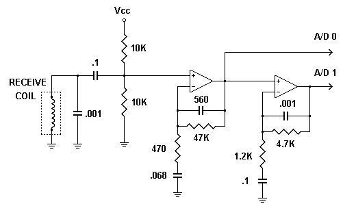
This is the preamp circuit I am using now. I had to make some alterations to White's design because I am using a single ended power supply while they use a double. The 10K resistors bias the signal at Vcc/2 to center it in the A/D range.
The first amplifier stage is basically White's design. It is a band pass filter with the upper and lower cutoff frequencies both approximately at 6600 Hz. This gives a gain of 1/2 Rf / Rin or about 50. In this stage the signal phase may be shifted by an amount that depends on all 4 components. White's puts a trimmer in there so they can adjust the phase shift to 0. I don't care about the phase shift in this stage because I will calibrate everything in software. The output of this stage goes to one of the A/D channels.
The second stage is similar. I want a gain of 4 in this stage, but I do not want any phase shift because I want both A/D channels to see the same phase. So I moved the upper and lower cutoff frequencies away from 6600 Hz. This gives no phase shift, and the gain is Rf / Rin. The total gain of both stages is 200. The output of this stage goes to a second A/D channel.
I have also increased the coil drive current to 15 mA. A penny on the coil now gives a 500 mV signal out of the first stage and 2 V out of the second. The low gain channel has a lot of headroom for strong ground signals or large targets before it overloads. The high gain channel has less headroom but gives more signal to work with on weak targets. I can now see a penny at 7 inches from the 5.3 coil.
Robert Hoolko
