Announcement

Collapse
No announcement yet.

HH Schematic revision - thoughts?

Collapse
X
 
  • Filter
  • Time
  • Show
Clear All
new posts

  • HH Schematic revision - thoughts?

    Hey again, all,

    I managed to get a copy of a nice schematic capture and router program (ISIS and ARES Pro with modules),
    so I've started 'playing' with the HH schematic.

    Been busy learning how to run the software, so this first attempt could use some 'peer review', please.

    All I've done so far is to replace the 7880 (IC1) with a virtual ground circuit (and re-route the power grid to accommodate it).
    ATM, I have the design set up for VCO only.

    The spice sim worked fine up to TP4 (after I added C15 to account for the coil model, however, C15 isn't in the routed layout).

    The small 'scope' with the colored wires is not part of the circuit, it's just for the modeling.
    Unfortunately, I don't have the spice model for the 74HC221's, so my sims had to stop there.

    I know it's not the cleanest drawing, but, hey, my first try. I'm sure those familiar with the HH can figure it out, np.
    Anyone see any major screw-ups? I know I still need to add connector blocks, etc., but I think the layout should work.

    I kept Carl's tags for signal in/outs and TPs, but not component tags or pwr.

    Click image for larger version

Name:	pcblnhh1.JPG
Views:	1
Size:	209.4 KB
ID:	366450

    I'm working on replacing the timing/clock circuitry with a PIC chip next.

    Any thoughts? Thanks, GTB

  • #2
    Oh yeah, the .DXF file

    Forgot to add the .DXF file for anyone interested...

    pcblnhh.zip

    I didn't add the DD option yet, since the sims couldn't handle it. Add or 'fix' it and re-post the changes if anyone feels like it. Anyway, I'm having fun!

    The stock HH is a competent machine, and so far it's nearly equal to my ML Eureka on small gold and definitely matches or beats it on the larger stuff (and it gives me a baseline to compare to while playing with this design).

    Carl hit it 'out of the park' for an 'experimenter's' platform, I think.

    Thanks again, Carl!

    GTB

    Comment


    • #3
      You've done something I've been playing with on the bench: replacing the 7660 with a virtual ground generator, and cap-couple the coil to the preamp. It seems to work OK.

      Couple of things... Q2 & Q3 appear to be upside-down... Q8 should probably have the additional PNP bias circuit, otherwise it's likely to drift a lot with temperature.

      - Carl

      Comment


      • #4
        Hey there, Carl

        "Q2 & Q3 appear to be upside-down... "

        You are right...I 'brain-farted' on Q2 & Q3, they were upside down. Weird thing about the change in the sim after I fixed that was that I was able to drop the capacitance on C15 down to 40pf for a nice (sim) waveform at TP4 (as opposed to 850pf with Q3 inverted). It's a wonder that it worked in the sim at all....

        "...replacing the 7660 with a virtual ground generator, and cap-couple the coil to the preamp..."

        The sims I've run also seem to suggest that the coil has to be cap coupled with this virtual ground setup. Why is that?

        "Q8 should probably have the additional PNP bias circuit, otherwise it's likely to drift a lot with temperature."

        It looks like gate C on IC7 is doing that for Q5 in the original HHvD1 schematic. Is that correct?
        Would I just add a similar PNP arrangement to Q8 and go straight to +5V on the emitter?


        I'm trying to catch up on this analog stuff, but as you can tell, I'm a bit behind (wish I could do the whole thing on a PIC chip...sigh).

        Thanks for the input and help, Carl (Hope the new job is workin' out cool!). GTB

        Comment


        • #5
          Originally posted by Carl-NC View Post
          You've done something I've been playing with on the bench: replacing the 7660 with a virtual ground generator, and cap-couple the coil to the preamp. It seems to work OK.

          Couple of things... Q2 & Q3 appear to be upside-down... Q8 should probably have the additional PNP bias circuit, otherwise it's likely to drift a lot with temperature.

          - Carl
          Hi
          That coupling cap in the front end of the pre-amp .. does that in anyway affect sensitivitiy... seems it may affect gain ??
          thanks

          Comment


          • #6
            Diode on Drain

            If you add a diode for example BYV28-200, in series on the Drain of Q5, you reduce the output capacitance of Q5, which helps to reduce the delay time.
            Together with the diode you also have to add a 50 to 100k resistor to ground, to drain the capacitance that accumulates between the diode and the drain of Q5.

            Tinkerer

            Comment


            • #7
              diode/Q5 and resistor

              Hey there Tinkerer,

              Is there any reason not to use say a 1N4003 as opposed to the BYV28-200 choice? Those I happen to have....

              Thanks, GTB

              Comment


              • #8
                Originally posted by GT Blocker View Post
                Weird thing about the change in the sim after I fixed that was that I was able to drop the capacitance on C15 down to 40pf for a nice (sim) waveform at TP4 (as opposed to 850pf with Q3 inverted). It's a wonder that it worked in the sim at all....
                Transistors will work if you swap C and E, they just don't work very well.

                The sims I've run also seem to suggest that the coil has to be cap coupled with this virtual ground setup. Why is that?
                Because when the coil decays, it will end up at "V+". But the preamp can't handle that voltage; it's input needs to end up at ground. Ergo, the cap.

                It looks like gate C on IC7 is doing that for Q5 in the original HHvD1 schematic. Is that correct?
                Would I just add a similar PNP arrangement to Q8 and go straight to +5V on the emitter?
                Yes.

                I'm trying to catch up on this analog stuff, but as you can tell, I'm a bit behind (wish I could do the whole thing on a PIC chip...sigh).
                Hammerhead II & III.

                Thanks for the input and help, Carl (Hope the new job is workin' out cool!). GTB
                It's fantastic!

                - Carl

                Comment


                • #9
                  Originally posted by Tinkerer View Post
                  If you add a diode for example BYV28-200, in series on the Drain of Q5, you reduce the output capacitance of Q5, which helps to reduce the delay time.
                  I don't see how this can be. The drain of Q5 still sees the same transient voltages, so it's capacitance still has the same effect. All you've done is add diode capacitance.

                  - Carl

                  Comment


                  • #10
                    Think it's ready...

                    Hey Carl,
                    Thanks for the help (again...and right on with the new job)!

                    I think I'm ready for copper so here's where it's at:

                    Click image for larger version

Name:	sch2.JPG
Views:	1
Size:	202.7 KB
ID:	321276


                    "If you add a diode for example BYV28-200, in series on the Drain of Q5, you reduce the output capacitance of Q5, which helps to reduce the delay time...Tinkerer "

                    "I don't see how this can be. The drain of Q5 still sees the same transient voltages, so it's capacitance still has the same effect.
                    All you've done is add diode capacitance.

                    - Carl "

                    Makes sense to me, so no diode or resistor.
                    Which reminds me, wouldn't the new resistor/diode combo add even more noise upstream of the pre-amp?

                    "The sims I've run also seem to suggest that the coil has to be cap coupled with this virtual ground setup. Why is that?...GTB"

                    "Because when the coil decays, it will end up at "V+". But the preamp can't handle that voltage; it's input needs to end up at ground. Ergo, the cap."

                    Interesting...told ya I suck at analog (but I am learning). At least I hope so....

                    Anyway, I hope to commit this to copper in a few weeks, so anyone with a HH improvement idea, feel free to chime in.

                    Good huntin' and thanks for all of the help, GTB

                    Comment


                    • #11
                      did it again...argh

                      oops... here's the .DXF so far:
                      sch2.zip
                      Later's, GTB

                      PS - R1 should be 100 ohms...bet there's a few more mistakes...

                      Comment


                      • #12
                        Your up early!


                        Hay! What is C-15 there for?

                        Comment


                        • #13
                          Hey homefire...just up late, playing with the schematic. Added DD coil config a few mins ago, but gotta get some shut eye.
                          Check out Carl's reply about C15, with a virtual ground it's a 'needed' thing, for the very reasons he pointed out. I never would have figured out why.
                          Take care! GTB

                          Comment


                          • #14
                            Fast switching diode

                            Originally posted by GT Blocker View Post
                            Hey there Tinkerer,

                            Is there any reason not to use say a 1N4003 as opposed to the BYV28-200 choice? Those I happen to have....

                            Thanks, GTB
                            The diode needs to be very fast switching. A 1N4148 works well with low power and low voltage flyback, but the limitation is the your pulse power.

                            Talking about pulse power. For river gold nuggets of small size, you do not need a lot of power, but you want more sensitivity.
                            You can obtain that by adding a series resistor with the coil, of about 30 Ohm and increasing the PPS to the highest you can.

                            Tinkerer

                            Comment


                            • #15
                              Originally posted by Carl-NC View Post
                              I don't see how this can be. The drain of Q5 still sees the same transient voltages, so it's capacitance still has the same effect. All you've done is add diode capacitance.

                              - Carl
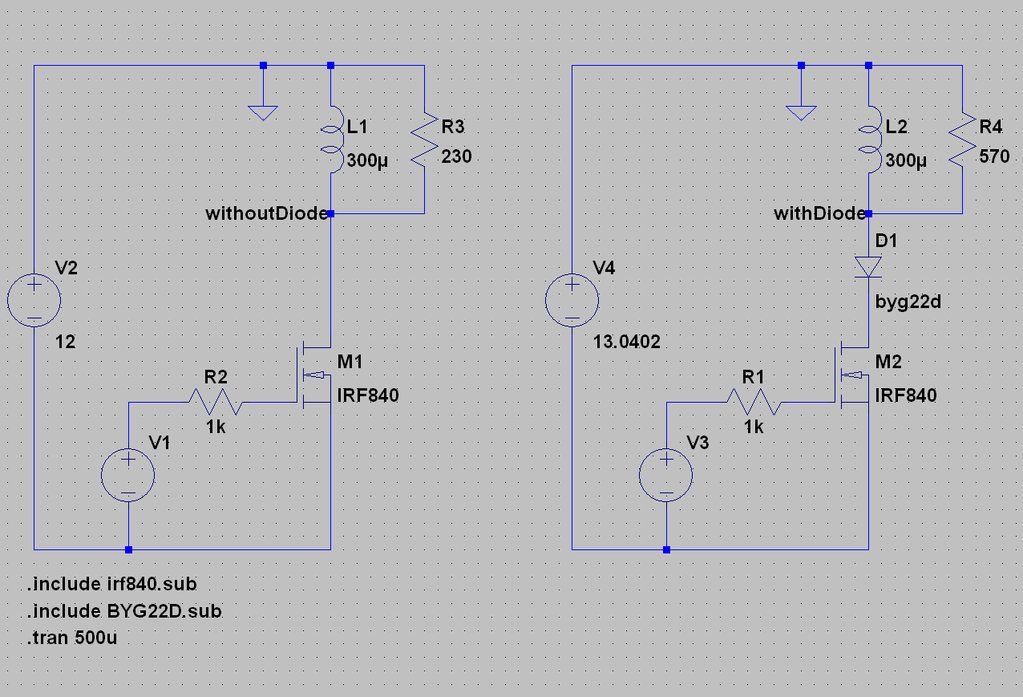
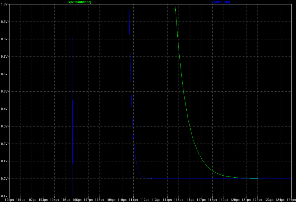
                              The diode capacitance is in series with the MOSFET's capacitance, so it serves to reduce the overall capacitance observed across the coil. I did some LTSpice simulations which proved the point. The simulation results held up in a circuit that I breadboarded as well. A discussion about it was held on another forum, but I can't seem to find the posts now. Aziz may recall where it was at, as I believe he was involved in the discussion as well.

                              Following are the simulation circuit that I used and the resulting simulated waveforms.

                              Some things to note are:
                              1) I increased the voltage in the diode circuit to match the coil current in both circuits
                              2) The optimum damping resistor value is much higher in the diode circuit, due to the lower overall capacitance


                              Comment

                              Working...
                              X