Announcement

Collapse
No announcement yet.

Is there a "better" way to connect ground return paths for separate Tx & Rx coils (PI)

Collapse
X
 
  • Filter
  • Time
  • Show
Clear All
new posts

  • Is there a "better" way to connect ground return paths for separate Tx & Rx coils (PI)

    I am not even sure if I am asking the right question, but here it is anyway:

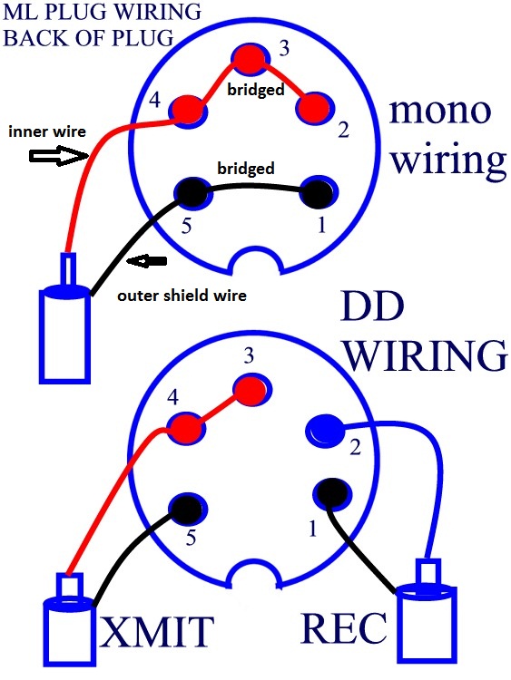
    Setup is separate Tx & Rx coils in a PI - MPP Rev E in this case.

    Does it matter how the return paths are interconnected or not?

    For me that would make at least the difference of having to get either 3 or 4 pronged plugs/sockets.

    What are your experiences with this?

    Nearly forgot, what is more prone to ground loops?

    Hope the drawing conveys what I mean:

    Click image for larger version

Name:	Plug_ground.jpg
Views:	1
Size:	83.5 KB
ID:	371023

  • #2
    I'll take a stab at this.

    It is important to provide separate paths to and from the two coils.
    Best if all the way back to the PCB.

    Connecting together at the connector, which is close to the PCB is probably fine.

    Do not run three wires to the coils (in coil housing). This would put TX current on the RX path.
    I'm guessing the coil is connected of the right and circuit enclosure is on the left.

    I do use 4 pin connector and run twisted pair wires on both TX & RX from coil to PCB. This has been working fine. The cable from the enclosure connector to the coils is CAT-5 so no shield, just twisted pairs. Inside the enclosure I run two pairs fo twisted wire (stripped out of CAT-5) from the connector to the PCB.

    A 4 pin connector would make it a little easier to solder damping resistors to the coil cable connector. One resistor for the TX and one for the RX.
    These are in parallel to a larger value damping resistor on the PCB. This way each coil built can be damped as needed and then allows simple coil swapping.

    Do you have 3-pin connector and need to buy 4-pin or do you need to buy either connector?
    If the later then buy 4-pin since this allows options.

    Comment


    • #3
      Not saying right or wrong. I use twisted pair for Tx and Rx + a single wire for the shield. 5 wires.

      Comment


      • #4
        Originally posted by green View Post
        Not saying right or wrong. I use twisted pair for Tx and Rx + a single wire for the shield. 5 wires.
        If using an electrostatic shield around the coils then a 5th wire is a good thing.
        This then has a separate path back to the circuit's 'ground'.

        Comment


        • #5
          Thank You waltr and green!

          I have yet to order plugs & sockets and will go for the 5 prong ones.
          That will leave all options open without having to order other ones again sometime.

          This is the type of cable I would use for a separate Rx Tx configuration.
          Wondering how waterproof it really is. The filling is cotton. Comments?

          Click image for larger version

Name:	Double_Coax.jpg
Views:	1
Size:	285.3 KB
ID:	353669

          I could use two twisted pairs as you say, but there is a lot of humidity & salty water around.
          At the moment I would not know how to get a good seal on those twisted pairs running to the coil.

          Just a thought: would running the grounds from the coil(s) directly to the battery be better than connecting somewhere to the PCB?
          Last edited by Polymer; 03-24-2019, 10:33 PM. Reason: Another thought :-)

          Comment


          • #6
            I as said, I use CAT-5 cable which has 4 twisted pairs.
            The outer 'plastic' jacket is water proof so would be like the cable you have is this regard.

            You just need to water proof the jacket to the coil shell.

            That is interesting cable and please post back here on how well it works for you.

            Comment


            • #7


              Here is the connections for milelab coils as well as TDI.
              I use a similar cable as your its a high end Audio cable mains shielded for in wall use.
              Also microphone cord is constructed in this manner makes a great coil wire.

              Comment


              • #8
                Originally posted by waltr View Post
                I as said, I use CAT-5 cable which has 4 twisted pairs.
                The outer 'plastic' jacket is water proof so would be like the cable you have is this regard.

                You just need to water proof the jacket to the coil shell.

                That is interesting cable and please post back here on how well it works for you.
                The blue S-Video cable I had used worked for a while. Saltwater has seeped into it.

                I have now tested many s-video cables which do NOT contain foil or any semi-conductive layers.
                Apart from being skimpy on the overall conductor thickness, the capacitance was very surprising to me.

                I measured the resonant frequency via the "parallel tuned circuit" oscillator & oscilloscope.
                Pinpointer coil measured for itself and then with connected s-video cable.
                Capacitor values used for testing in the tuned circuit: 0, 75pF, 150pF & 1000pF.

                The values were horrible (PP and measuring wire capacity is already deducted):

                The best one had 105pF/m
                Most had the range 125-145pF/m
                The worst one was a special studio cable with a whopping 185pF/m

                So no more s-video cables for me any more.
                I am looking into Mogami cables for outside use at the moment, they have clear technical data sheets IMO, Not just some Audiophile MumboJumbo.
                I will be grabbing some samples when travelling in a few weeks.

                Just read in one of these threads about PUR cables for seawater use. I will also be looking into that.

                The adventure continues ...

                Comment


                • #9
                  Originally posted by godigit1 View Post


                  Here is the connections for milelab coils as well as TDI.
                  I use a similar cable as your its a high end Audio cable mains shielded for in wall use.
                  Also microphone cord is constructed in this manner makes a great coil wire.

                  Thanks Godigit1.

                  It looks as though both ML & Whites do not have an extra shield wire return.
                  Or don't they use shields in the coil? Or maybe connected together in the outside plug?

                  This "how to wire the shield" business is driving me batty at the moment.

                  NOT needing an extra shield wire back to the detector housing would make it much easier to find suitable cables.

                  Comment


                  • #10
                    Pins 1 and five are connected in the plug and in the coil and the shield wires are connected to the junction in the coil.

                    Regards, Ian.

                    Comment


                    • #11
                      Originally posted by IBGold View Post
                      Pins 1 and five are connected in the plug and in the coil and the shield wires are connected to the junction in the coil.

                      Regards, Ian.

                      Thanks Ian!
                      I feel like I am slowly getting a clearer head on this.

                      In the light of mistrusting my own rooky measurements comparing:
                      - separate GND return paths to the PCB from Rx/Tx/Shield
                      - GNDs of Rx/Tx/Shield connected together in the coil with only one return path thru cable to PCB,

                      I am wondering if detector manufacturers do it the "easy" way because:
                      - it doesn't really matter technically OR
                      - it is cheaper with more margin for the company regardless of possible disadvantages.

                      Any insights on this anyone?

                      Cheers, Polymer

                      Comment


                      • #12
                        So, I've continued going down the rabbit hole of grounding/shielding.
                        Found the following, am not sure it's fully applicable to our faraday-ish application of shielding of coil / pcb-housing
                        Comments, Insights ?

                        https://www.emcstandards.co.uk/cable...t-one-end-only

                        Click image for larger version

Name:	figuress_large.png
Views:	1
Size:	67.8 KB
ID:	356604

                        Here the copied Text, so it sticks here in the forum:

                        Cable Shield Grounded At One End Only

                        Author: Larry West
                        Low Frequency RLC Model

                        Contributed by Larry West: ([email protected])
                        The myths that (1) a cable shield grounded at one end only (single point gnd, SPG) is really a shield and (2) that a shield grounded at both ends creates an unwanted ground loop have been asinine EE folklore for decades. Both are dead wrong. An SPG cable shield is a hi-pass filter to magnetic fields and a lo-pass filter to electric fields with amplification at the break frequency. Alleged ground loops exist before shields are considered. A properly grounded shield simply does its job -
                        attenuate. Cable shielding and ground loops must be disassociated. People with no knowledge are fictionalizing a problem they don?t understand. Ground potential differences must be attacked with proper isolation techniques not wrongheaded shielding. ?Grounding? a cable shield is a misnomer; cable shields should be ?bonded? to the enclosures their cables arefastened to.

                        A cable shield grounded at one end only (single point ground, SPG) is depicted in Figure 1. Alsoshown isan electric field perpendicular to the cable and a magnetic field perpendicular to the plane of thecable and its image in a ground plane (both for maximum coupling). The figure shows a coaxialcable however it is intended to represent any cable with any number of shielded conductors.

                        Figure 2 is a simple RLC circuit model of the SPG shield coupled to an electric field, E. There are four parameters associated with this coupling model, the shield to groundplane capacitance, C2, the shield to shielded wire capacitance, C1, the shield inductance, L1, and the shield resistance, R3. For the purposes of this exercise, the parameters have been chosen to be representative of a 15m long cable that has a quarter wave resonance at 1MHz. Both loads are 1kΩ. The electric field couples to the line through the line to ground capacitance as a Thevenin equivalent source, VOC = E?h, where h is the height of the line above the groundplane. Other parameters like wire resistance have been suppressed because they are not part of the shield RLC model and less than the loads. The shield resistance, R3, has been increased so that the resonant Q-factor is Q ≈ 10, the most usually seen. It is difficult to model actual losses analytically therefore the Q-factor has been used to arrive at a shield resistance.

                        Figure 3 is the same RLC model of an SPG shield coupled to a magnetic field, B, with the voltage, V OC = iω?l?h?B, where l is the length of the shield.

                        Figure 4 is the combined results of the two coupling models. The effect of the SPG shield is exactly what the RLC model suggests; that is, the SPG shield is a low pass filter for magnetic fields and a high pass filter to electric fields. The filters? break points are both at the frequency corresponding to the shield length being one quarter wavelength. The SPG shield is therefore not a shield at all. Shielding effects are orders of magnitude below these curves. The last point is that the
                        SPG resonates so that the induced signal is amplified, not attenuated, at the shield?s resonant frequency. This model is a low frequency model however all of the relevant parameters are included.

                        The multitude of app notes and articles on this subject that recommend grounding the shield at one end only misrepresent the physics of shielding and falsely ascribe a ground loop to the shield where the circuit itself was part of the original ground loop. Cable shielding and ground loops must be disassociated. Grounding the shield at both ends attenuates the coupling to the shielded wires by approximately the ratio of load current to shield current, SA ≈ Iload/Ishield ≈ ZT?l/2?Zload,
                        where ZT is the shield transfer impedance, l is the length, and Zload is the load resistance of both loads. As an example, a cable shield with a DC resistance (and low frequency transfer impedance, ZT?l = Rdc) of 1Ω and load resistances of 1kΩ will have a low frequency shield attenuation of approximately 5?10-4 or 66dB.
                        The shields should be ?bonded? to the boxes at the ends of their respective cables, not earth ground, building ground, or anything else. Military standards like Mil-Std-188-124B and the FAA get it right. It?s time for everyone else to also.

                        The following is litany of very bad advice from otherwise reputable sources:

                        (1) EE Times, ?Control System Grounding - Part 2: Ground Wiring, Shield Grounds, and Power Supply Grounding, Shield Grounds?, Roger Hope, Dave Harrold, and David Brown, 7/15/2008: A proper shield ground path is to ground the shield at one end only.
                        (2) EDN, ?Grounding and Shielding: No Size Fits All?, Martin Rowe, Senior Technical Editor - August 1,2001; Never connect a shield to ground at both ends. Doing so would create a ground loop.
                        (3) Analog Devices, Analog Dialogue 17-1, 1983, Alan Rich, ?Shielding and Guarding, How to Exclude Interference-Type Noise, What to Do and Why to Do It ? A Rational Approach?: Don?t connect both ends of the shield to ground.
                        (4) Wikipedia, Shielded Cable: The common method to wire shielded cables is to ground only the source end of the shield to avoid ground loops. Wikipedia!!??
                        (5) LTC486 Data Sheet: The optional shields around the twisted pair help reduce unwanted noise, andare connected to GND at one end.
                        (6) Maxim Integrated, TUTORIAL 2045, Understanding Common-Mode Signals: For any shielded pair(s) carrying balanced signals, you should connect the shield to ground at one end, usually the receiving end.
                        (7) web www.bobtech.ro, Wiring Guidelines for RS-485 Networks, Application Note 001, Grounding: If shielded twisted pair cable is used? , the shield shall be connected to earth ground only at one end. ( B & B Electronics, RS-422 AND RS-485 APPLICATIONS EBOOK, Shielding: If shielded cable is used, the shield should be grounded at one end only, preferably to earth ground.
                        (9) Alpha Wire, www.newark.com/pdfs/techarticles/alphawire/ USC.pdf, Understanding Shielded Cable:Ground the cable at one end. This eliminates the potential for noise inducing ground loops.
                        (10) eeeic.eu/proc/papers/ 55. pdf , Cottbus University of Technology, Germany & Wroc?aw University of Technology, Poland, Anke Fr?bel, ?Cable Shielding to Minimize Electromagnetic Interference?, III. CABLE SHIELD GROUNDING: If a shielded cable is used to connect two systems, the shield has to be connected to a single ground reference. In order to prevent that electromagnetic energy penetrates through the shield, the outer surface of the shield has to be grounded. At low
                        frequencies for E-field excitation it is more efficient to ground both ends, whereas for H-field excitation one end grounding has to be favored, since this eliminates the formation of a current loop by the cable and the ground plane. At high frequencies both ends grounded configurations avoids resonances for E-field and H-field excitations. In practice one ground connection is often preferred, since this avoids ground loops. However, for short cables, at low frequencies, the voltages induced by EMI at both ends of a coaxial cable become nearly equal and one end grounding
                        is needed for E-field as well as for H-field excitations. [I included this to show how confused people are about this subject. The author tried to write about shielding but only displayed his ignorance of the subject. He even got the E-field and H-field shielding reversed.]
                        (11) www.calex.com/pdf/4ground_shield.pdf, This article was written for CALEX by Mr. Ralph Morrison, President of INSTRUM and the author of Grounding and Shielding Techniques in Instrumentation published by Wiley; Grounding and Shielding: The input cable shield cannot be grounded more than once. [With figures, only, Mr. Morrison shows the other end of a cable shield connected to ground
                        through a 10MΩ resistor. ?From the jaws of victory??]

                        Comment


                        • #13
                          Waltr, you mean you are using standard cat-5 cable the same we use to hook up wifi and internet services,but the better insulated outside blue cable and not the brown cheaper stuff, so are you twisting a pair together and using it as one wire, so a 8 wire will give you 4 standard wires and now you have color coding and each wire would be insulated.

                          Comment


                          • #14
                            I have been using the White CAT5 but Blue should be the same.
                            Yes, the high quality CAT5 for Ethernet connections (WIFI, etc).

                            There are four twisted pairs in CAT5. I use two Pairs, one for TX and on for RX.
                            So only use 4 wires. The other four I cut short.

                            CAT5 has foil shield with a drain wire. This wire connects to the connector shell.
                            The connector I use is four pin.

                            Comment


                            • #15
                              I may have missed this somewhere in the thread but do you use CAT5 that is stranded or solid?

                              Comment

                              Working...
                              X