
 Tweet
Tweet
Carl : I originally thought this machine would be using solid aluminium wire, likely near-pure electrical grade, with high conductivity, 65% IACS. I have some lengths of this stuff, 8mm diameter insulated, I salvaged it for just such a project. I've also recently rescued a decent reel-end of lightning-conductor strip. Again aluminium, insulated, about 4mm x 22mm, electrical grade. Good project material, but the toroids would need to be large ( though there is the pot-core transformer way of doing it ).
-
-
That's why I thought of copper rather than aluminum.Originally posted by Davor View Post
It is easier to shape, easier to process, easier to solder ...
Somewhere deep inside me there is still a radio amateur from the late eighties ... a lot has not been forgotten yet...Comment
-
It is more better the electrical connection with copper than aluminium , also aluminium oxyde white baddly around the nuts connection!!!Comment
-
i had an idea about the piping, there is an alloy used in pipe work that is used where stronger and lighter materials are needed, its used for car and lorry brake pipes(cunifer), its lighter than steel and does not rust, and is a lot stronger than copper, its main benefit is that the tube walls can be thinner than copper for a given diameter.Originally posted by ivconic View Post
i have used this for years in cars because replacing steel with this means it will never need changing again, its available in short runs you would need a few meters only.
as an alloy of copper and nickel it will solder and might be a better match for your coils too.
hope this helps.
aly.Comment
-
The problem with CuNiFer could be the low conductivity, I think. Copper alloys that have nickel in the mix tend to be really poor conductors ... cupro-nickel being the obvious example ( US 5c coin, many UK coins like 50p ). The nickel-bronze of our UK Pound coins is another example.
It's definitely a strong alloy, and the brake lines are available in 8mm and 10mm O/D , as well as the thinner 5mm,6mm typically used on car brakes. The 5mm size can be bent just by hand, but the 8 / 10mm could require a pipe bending jig and skill to get correct.
( it's normally taken off a reel, so it's naturally almost circular in shape, which may be handy for Ivconic .. )Comment
-
Or...
I just have found nice local offer of Cu bars (not pipes).
Thing with the bars; those will bend nicely unlike pipes.
https://metalionline.com/bakarna_%C5...a_okrugla.html
10mm bar, 1m length = 0.707kg
Original TF-900 coils, overall length = 2680mm
2.680x0.707= 1.890kg... only bars.
I just measured originals, bars mounted on stems: 475+495g = 970g
Huh!
Cu bars only, without stems; 1.890kg vs Al bars with stems 970g!
Obviously why Al was choosen.Comment
-
"Huh!"
As I thought ...
-------
Regarding the Cunifer cupro-nickel alloy specs:
It's roughly 90% Cu / 10% Ni, but the added iron ( and a little Mn ) make it more like 89 Cu / 10 Ni / 1 Fe.
A bit of searching produced a conductivity value of 9.6% IACS, or 5.5 x 10^6 S/m ( or Resistivity = 0.18 x 10^-6 Ohm.metre ),
which is low, not much different to lead ( 8.4% IACS ) , and a long way from electrical aluminium, (62 - 65% IACS).
Source of copper-nickel alloy data:
https://www.copper.org/applications/...I_booklet.html
-------
Don't forget Skin Effect. The solid aluminium ( or copper ) bar will not all be conducting, mainly just the outermost 1 -> 2mm , even at a fairly low 6.95 kHz operating frequency. Skin effect is most noticeable in good electrical conductors, eg. pure copper, pure aluminium. In poor conductors like lead, it's 3 times deeper. ( it varies with the square-root of the conductivity, I recall )Comment
-
Comment
-
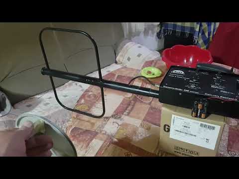
Finalizing few small details and wraping it up, it's done.
Comment
-
Skippy you cursed me! I just put it all together and closed it, the first time, I turn it on... and it works "upside down"! So I had to open everything up again and swap the wires on the RX!
I have to take care not to mess with you in the future!

Comment
-
Annealed copper is very soft. Guess using a braid over a plastic form would do the trick. But it smells like a lot of work.Comment
-
Nice to see it all working. That 'upside down' mode could be useful for finding caches of highwayman money hidden in trees!
Do you have any way of properly testing out it's performance, for example comparing its depth with another two-box machine on some 'standard' targets ?
I am a bit concerned that the use of those green toroids may have lowered its performance. Also, we don't know if the RX and TX should be carefully tuned to the same frequency ( by adding capacitors / or adding/removing wire turns from a toroid ), or intentionally de-tuned by a precise amount. So there may be ways to get more out of this machine.
Did you measure the transmitter frequency ? I was curious about how much the big TX loop would affect things. The L and C tuning components suggested a higher frequency than the specification of the complete detector.
-----
If you have time, it would be appreciated if you could tell me the dimensions of the antennas, and the spacing apart of them. They look slightly rectangular in the photo? This would be useful when I eventually try my maths simulation of a two-box.
-----
George: Sorry for not replying to the simulation experiment post. The more I think about it, the more ways I can think of modelling the loop. One turn or half-a-turn? Good coupling 90%, or poor 50%?Comment
-
I don't have the conditions right now. This is the worst time of the year to go out in the field. Infernal heat and highly elevated radiation.Originally posted by Skippy View Post
I go down to town to get groceries, for half an hour... and then I feel bad all day. So I avoid going outside when it's hot like this.
Something is wrong with the climate, something has been changing drastically for the past few years. These aren't the summers they used to be.
So I can only evaluate the performance of the detector based on my rich experience. I had a TM-808 (two pieces spanning 20 years), a Fisher Gemini II,
a couple of older 2boxes whose names I can't remember...
And I still have a Garrett Master Hunter with 2box assembly in the attic (albeit broken).
Based on all that has been said; I would say that this TF900 works very correctly.
That's why my tests are not detailed, but I made a video just to show that it works.
In room conditions, it is impossible to test the detector well, especially not the 2box.
I have hand drawn sketches of the dimensions, I will transfer it to some program and draw it to make it better. Then post here.
The frequency is 12.xx kHz.
You may have missed a detail when I wrote that I measured and cut two 100% identical pieces of wire. Then wound both on both green toroids.
It is crucial.
It is important that those two LC tanks have as similar a resonance as possible.
Everything else is less important.
And the frequency is determined by those 2x14 windings.
In this case they are 2x12 because the greens are a little taller than the originals.
I will post the dimensions a little later.Comment
-
Since the loop is a single turn, it will act as a short-circuit when added with coupling coefficient of unity. In that case the circuit fails to oscillate. However, it is also clear that the loop is not tightly coupled to the core, which is why I set K to 0.85. This is a bit of a compromise, because trying to couple the loop separately to the core with a different K value doesn't work as this represents a non-physical winding configuration to the simulator.Originally posted by Skippy View PostComment
-
Comment
Comment