If this is your first visit, be sure to
check out the FAQ by clicking the
link above. You may have to register
before you can post: click the register link above to proceed. To start viewing messages,
select the forum that you want to visit from the selection below.
Hi!
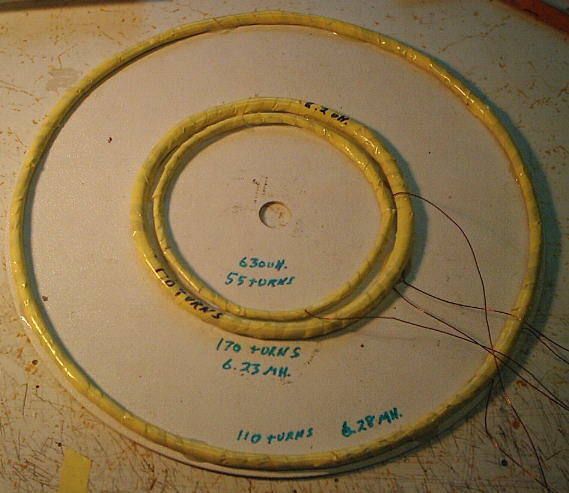
It is my variant Concentric Coil with the agreeing ferrite transformer for VLF detectors.
Feature - ferrite transformer adjustment Coil
I yet did not test Coil to the detector. With use of the external generator of signals 8 kHz Coil is adjusted well.
Adjustment of suppression of a signal - selection of coils of the transformer
That's an interesting way of getting around having to make a bucking coil!! Very interesting!!! I wonder why the coil manufacturers haven't thought of that. It sure could make tuning a lot easier. Thanks for posting your idea!!!
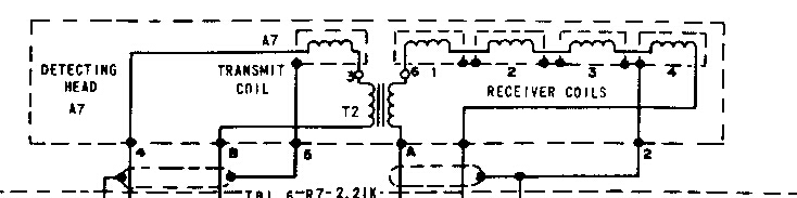
very interesting....I add to your diagram some additional construction information like start and end of the coil winding direction. Does it match to your test arrangement? What kind of ferrite transformer you use (N=1:1)?
If this method works well and if they knew about it back in the '70's why do they still use the bucking coil arrangement in concentric coils instead of this method? It seems that it would be much easier to build physically and much easier to tune electrically than the bucking coil method. I would think that there must be some drawback to this method or the detector manufacturers would have adopted this method for making thier own coils. Does anyone know the answer?
I tested 2 ferrite rings by a diameter 25 and 45 mm of the unknown mark.
Number of coils of the transformer
1 winding - 18 coils
2 windings - 9 coils
Wire by a diameter of 1 mm - some wires in plastic isolation.
I think, that the diameter and mark of a wire of the large meaning(importance) has no
From a beginning L1 and L2 are adjusted in a resonance on working frequency with the help Ñ1 and Ñ2, following
Adjustment of suppression of a signal make by change of number of coils of 1 winding
 Tweet
Tweet


Comment