
 Tweet
Tweet
I tried to build a coplanar coil. the transmit coil consists of 88 turns of 0.51 mm (25swg) enamelled copper wire,for a diameter of 22.5mm. The bucking coil consists of 27.16 turns of 0.51 mm (25swg) enamelled copper wire rolled up on the reception coil of 270 turns of 0.2 mm enamelled copper wire and for a diameter of 11.5mm. The assembly is made to work at 10khz. I respected the indications given on the site for the coplanar coil construction but that does not work. after several tests with an oscillator, I can't obtain the balance with the bucking coil. Somebody could help me to find what does not work in this assembly
-
-
Re: some errors
I tried to build a coplanar coil. the transmit coil consists of 88 turns of 0.51 mm (25swg) enamelled copper wire,for a diameter of 22.5cm. The bucking coil consists of 27.16 turns of 0.51 mm (25swg) enamelled copper wire rolled up on the reception coil of 270 turns of 0.2 mm enamelled copper wire and for a diameter of 11.5cm. The assembly is made to work at 10khz. I respected the indications given on the site for the coplanar coil construction but that does not work. after several tests with an oscillator, I can't obtain the balance with the bucking coil. Somebody could help me to find what does not work in this assembly -
Re: some errors
Leaud,
1, Make sure that the tuning capacitor in your LC oscillator is across the series connection of the transmit and the bucking coil.
2, Try reversing the connections to the bucking coil.
3, Try adding and removing some turns of wire to the bucking coil.
4, If all else fails, read the White's patent on this site. See link below. Good luck . . .
Click HereComment
-
Re: some errors
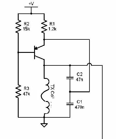
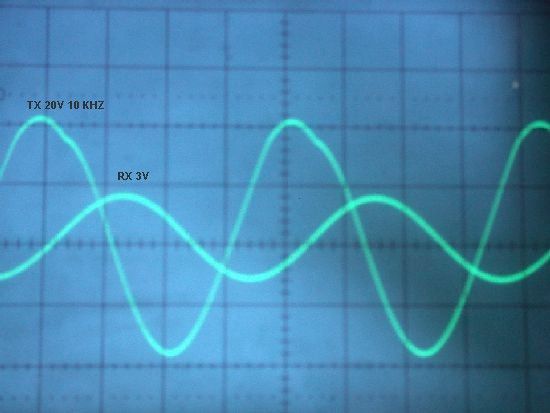
I send the oscillator that i use and the signal that I see on the oscilloscope, with out metal near the coilsComment
-
Re: some errors
Comment
-
Re: some errors
Leaud
I have to second exactly what Dave Emery replied to your earlier post. Looking at the amplitude of the receive signal from the coil it sure looks like the bucking coil is wound in phase with the TX coil. I just made my first concentric coil myself and got esentially the same thing as you till I reversed the leads on the bucking coil. It then dropped to 2mvpp on the receive coil. Another thing is are you sure that there is no metal anywhere close to the coil? I don't believe that I am getting as good of a null as I should even the 2mv signal is almost 6 volts peak to peak out of the amplifier. The extra half turn left loose between the TX coil and the bucking coil has almost no effect on the null in my coil no matter where I move it. I also read the patent that Dave referred to. I tried the placement of a shield between the receive and bucking coil, grounding it to the ground side of the TX coil. The null actually got worse. My next step will be to remove a few turns from the bucking coil to see if the null improves or gets worse. Good luck and let us know how you made out.
HH
Russ_NYComment
-
Re: some errors
Leaud,
Sorry it took so long for me to answer but I have illness in the family. Check to make sure that the bucking coil is connected the right way. Simply reverse the connections to it and see if things get better. Make sure that you have two seperate shielded cables or a length of S video cable to connect your coils. DO NOT connect the shields together at the coil end of the cables. multi stranded cable with a single shield is also not suitable for balanced coils. I use two lengths of RG174 miniature coaxial cable.Comment
-
Re: some errors
Russ,
Let me quote from the patent:
After nulling the receive coil output under balanced conditions should is less than 6mV pk to peak amplitude and has a lead phase difference relative to the transmt signal of 40 to 100 degrees.
For a 2mV signal to cause a 6 Volt output from your coil amplifier you must have a gain of around 3000. Woof!!! That is way too much for a VLF and extremely high for a PI. You need to reduce the gain and lower the output signal.
Your coil sure aint broke so don't try fixing it. Indeed it would seem that you have done a great job with it.
Did you build the coil as a VLF or PI coil? If you make it for a VLF I would be curious to know what frequency you put it on.Comment
-
Re: Dave, oops left out the decimal point
Dave,
What a difference a decimal point makes. Sorry that should have been .6 volts not 6 volts out of the preamp. The coil is for a VLF detector, probably some version of the Bandito. At present I only have the TX oscillator and receive amp on breadboard. I wound the coil to run at 10 Khz. This coil resonates at 9.88 Khz with the component values from the Bandito schematic. I could adjust the frequency but I really don't see a good reason to. I made this particular coil to do some experimenting with. The coils are wound on forms made from hardboard, which I turned on my lathe. The forms are impregnated with wax so that the adhesive I use to secure the windings doesn't stick to them when I split the form halves to remove the coil. The base for the coil assembly is turned from a piece of 3/8 inch ABS with 1/4 inch high concentric ridges for the TX and RX coils. The Bucking coil is wound seperately and fits very snugly over the OD of the RX coil. I wanted it to be as precise as possible so I could get some good data with it. I want to look at the various phase relationships between different types of ferrous and non ferrous targets as well as how mineralized ground effects the signals. I have read quite a bit about the phase relationships and think I understand it for the most part. I think being able to actually visualize it myself by doing some experiments will help me to have a better understanding. I have also built a couple PI prototypes. The last coil I built for the PI runs on the bench with a slightly under 10uSec sample pulse. I hope to have fully functional versions of both the PI and the VLF ready to test outdoors by the time the snow and ice finally go.
HH
Russ_NYComment
-
Re: Dave, oops left out the decimal point
the bucking coil is connected the right way and I don't use a separate shielded cable.I followed your advices, I unwound some turns on the buking coil. the signal then dropped to 1 Vpp on the receive coil without metal near the head.The extra half turn left loose between the TX coil and the bucking coil has almost no effect on the null in my coil, I don't know why. I built this head for a VLF detector for bandido.Comment
-
Re: Dave, oops left out the decimal point
Leaud
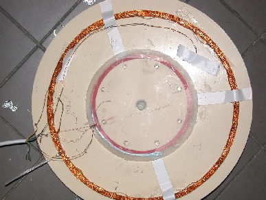
Looks like you did I nice job. I would change the cables to seperate shielded ones. I also use the small RG 174 for both Receive and Transmit. What do you have the Receive coil connected to, and what capacitance do you have across it? It's difficult to see for sure but is that a metal screw in the center of the coil assembly, and what are those 8 small round things around the outside of the receive coil form? I can't tell from the picture, is that the wire color or do you have the TX coil shielded? It looks almost like copper foil. Other than changing the bucking coil 1/2 turn at a time and retesting I don't have any other suggestions.
Good Luck
Russ_NYComment
-
Re: Dave, oops left out the decimal point
The receive coil is connected to nothing there is just a 100nF cap connected in parallel. In the center it's an acrylic resin screw and the 8 small round things around the outside are 8 holes. the TX coil in not shielded it's the wire color.Comment
-
Re: Dave,, I messed up again
I must be getting wacked in my old age. I checked everything again this morning and with a 2mV null at the coil I get 60mV out of the amp. I must have been looking at the 10X probe indication rather than the 1X which is what I was using. Sorry for the confusion
HH
Russ_NYComment
-
Re: Dave, oops left out the decimal point
leaud , You MUST use separately shielded wires for both the transmit and the receive coils. a single cable with both the transmit and the receive wires inside will not work. Also, it is a VERY bad idea to tune the receive coil with a capacitor. There are many reasons for this including the fact that your discrimination settings will drift with temperature. For testing you can use regular radio/TV coaxial cable such as RG59 etc. The impedance does not make any difference as you are using audio frequencies. The partial turn of wire will only have an effect when your coil is almost completely nulled. Good luck and let us know how you are making out.Comment
-
Re: Dave, oops left out the decimal point
Russ, Please send me an email so I can send you one, Dave. * * *Comment
Comment