Announcement

Collapse
No announcement yet.

Is there an inductance formula for DD coil, is there a "Wheeler" equivalent?

Collapse
X
 
  • Filter
  • Time
  • Show
Clear All
new posts

  • Is there an inductance formula for DD coil, is there a "Wheeler" equivalent?

    Hi,


    I'm building my first E-trac coil. I took some measurements of the Minelab stock coil with my RLC meter. Here is what I got when measuring the coil's output pins 1 thru 5:
    1. pins 1 & 2 Resistance = 1.1ohm, Inductance = .54mh
    2. Pins 3 & 4 Resistance = 5.8ohm, Inductance .69mH
    3. Pin 5 Resistance = open with all other pins (drain pin)
    I'm using Barry's Inductor Simulation to determine what guage of Magnet wire to use.
    http://www.coilgun.info/mark2/inductorsim.htm

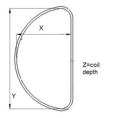
    However I want to build a D-coil. How to componsate for the change in geometer from a perfect circular shaped inductor to a D shape coil? Is the a Wheeler's equilavent formula to model the following parameters (X,Y,Z) as shown in the attachment?


    Thanks,
    Majesus

  • #2
    I once asked the same question. The answer I got was something to the effect, measure the overall length of wire in one winding of one D section and substitute that number for circumference in the formula:

    diameter = circumference/pi.

    Then, plug diameter into your favorite coil calculator. (Why didn't I think of that??)

    It might be simplified but you will be in the ballpark. Somebody with more time and motivation than I could maybe work out a useful 'k' factor to apply to the result.

    Comment


    • #3
      Simple enough.

      I can model the coil in Autocad to see how I like the inner geometer and then determine the circumference from it.

      Then use the following calc to get my AWG and outer dimensions.
      http://www.circuits.dk/calculator_mu...er_aircore.htm

      Gives me a starting point.
      Thanks

      Comment


      • #4
        I did some experiments along these lines last year. I made a circular coil, measured its inductance, and then re-shaped it to a rectangle, with approx 2:1 aspect ratio. The coil L was remeasured.
        Details were: 100 turns of 0.25mm diam ECW.
        Circular coil, diameter 48mm: L =980 microhenry.
        Reshaped coil, 55mm x 28mm: L = 880 microhenry.
        Note: the rectangle shape has rounded corners, bend radius approx 6mm.
        So L is reduced by 10 percent in this case. I think the reduction for a D coil will be less, probably 5 to 8 percent.
        Hope this helps.

        Comment


        • #5
          I've just thought some more about this, and have worked out the theoretical size of a D coil made from my example coil (above). It's actually very similar to my rectangular coil, so maybe an L reduction of about 10 percent is a fair approximation when going from a circular to D shape with the same circumference.
          Maybe you could wind a crude test coil with less turns, for example, on your former, then measure its L and use this data to guide your final coil design.

          Comment


          • #6
            Now that I can ball park the AWG I need, I was going to wind it, strip just a little of the insulation to measure while on the JIG. If I need more turns, revarnish the nick and keep winding.

            5 to 10% from a circular coil to a 2:1 D coil. Hmmm, I'll take some measurements once I CAD the geometery and compute the diameter as per porkluvr's suggestion and calc the inductance using an inductor calc.

            See if the inductance is 5 to 10% different.

            Comment


            • #7
              Re: Minelab stock coil

              Majesus, do you have a signal generator and oscilloscope to measure the resonant frequencies of windings in your Minelab stock coil? What is the overall diameter and weight of Minelab coil?

              Comment


              • #8
                The other thing you could do, of course, is when you wind your coil, bring out a couple of taps near the end. This will allow you to fine-tune after winding and varnishing,etc. Example wind with 40+2+2, this allows 'ideal' +/- 10%. If you isolated the extra winds, you could join them back in reverse, ie. winding 40 & 2+2 would allow 36,38,40,42,44 T coil. Hope this helps.

                Comment

                Working...
                X