Announcement

Collapse
No announcement yet.

Which IGSL, Musketeer, or TGSL coil??

Collapse
X
 
  • Filter
  • Time
  • Show
Clear All
new posts

  • #16
    Originally posted by bernte_one View Post
    can you show where you put batteries
    i take everytime an external battery box
    but yours seems to be inside
    did open screws everytime for change batteries?

    regards

    @bernte_one

    12V 1800mAh Rechargeable Portable Emergency Power Li-ion Battery

    http://www.dealextreme.com/p/12v-180...-battery-54201

    Comment


    • #17
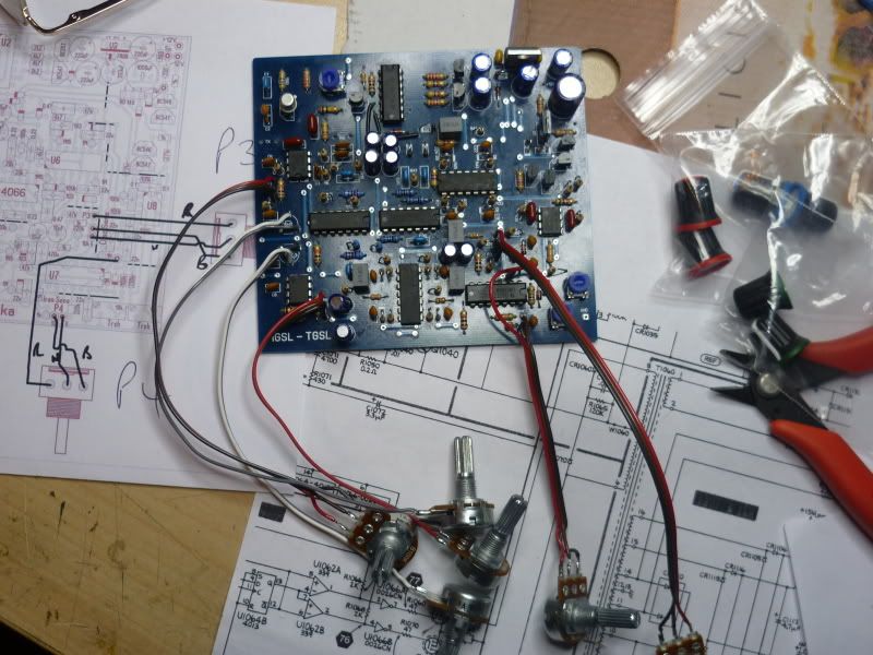
      Ok, TGSL board nearly finished!!!!!!!


      And took above advise, I purchased a Tesoro Deepscan, 5 pin coil,... (EBay...)

      Just need to wire it in,........ Now, I have hunted, and hunted, {Cos I know Carl has posted a diagram of the standard 5 pin wiring,...}, but I cant find it,........ can anyone link me to the pinouts of the standard, 5 pin, Teroso coil?????

      Cheers, Fred

      Comment


      • #18
        Originally posted by Comp View Post
        Ok, TGSL board nearly finished!!!!!!!


        And took above advise, I purchased a Tesoro Deepscan, 5 pin coil,... (EBay...)

        Just need to wire it in,........ Now, I have hunted, and hunted, {Cos I know Carl has posted a diagram of the standard 5 pin wiring,...}, but I cant find it,........ can anyone link me to the pinouts of the standard, 5 pin, Teroso coil?????

        Cheers, Fred
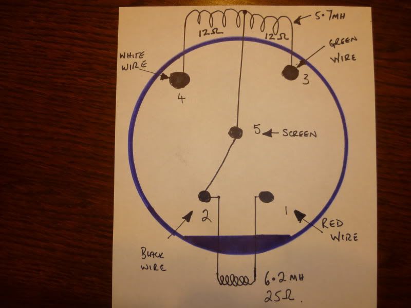
        Here it is:
        Attached Files

        Comment


        • #19
          Thats the one!! Thank you so much,

          Cheers, Fred

          Comment


          • #20
            Ok, got home from work today, coil has arrived, I was feeling pretty tired, but just had to wire it in, & have a quick play!!!!

            First, I set all the pots to mid range, and powered up!! The board fired up, gave a little bleep, and sat waiting for me!!! I waved a screwdriver at it, and it gave a low beep, my wedding ring gave a high beep, so something aint too far off!!! A quick peep on the coil with the scope shows it is running at 16.2 Khz, some 15V P to P, tweaked the trimmer for a nice sine wave, and a quick run round with the meter.
            The sensitivity is low, but I havent tweeked anything yet, and the minus supply line is only minus 3.75V, and the supply current seems high at 120ma, but I know I will blow something if I poke about it, while I am tired, so, time for a glass of vino, and put my feet up, look at it over the weekend!!!!

            Cheers guys, will keep you updated,... Fred

            Comment


            • #21
              Ok, I KNEW as soon as I started work today, I shouldn't work on the MD,... ( I am a Postie, & I got badly bitten on my leg, first thing!!!!! L:OL!! )
              But, decided to try for an hour or so, after lunch......

              Took me a fair while, but found the low minus supply was my fault,.... I had used a 74HC4066 for the quad switch,.... I eventually realised it was 'pulling down' the supplies, and also causing the high current drain. Popped to the local Maplin for a Cmos 4066, and that sorted that.

              Now, the coil............... I was struggling to make it work,... I eventually stripped the plug off, and had a good run round with the multimeter. Turns out, not to be wired up, like the diagram above. This is what I found......


              I can only get it to run if I use the 6.2mH winding for the Tx, and the 5.7mH as the Rx, with the screen earthed, obviously the Rx coil is centre tapped to Earth.
              This causes the system to run at 16.2 Khz, but it does work, all be it at low sensitivity/range.
              So, Question, is it possible to strip the coil covers off, and shift the shield to where I need it, or am I stuffed??? HELP!!!

              Thanks for any & all input, Fred (the newbie!!)

              Comment


              • #22
                I've opened more then a few coils by going around the seam edge with a Sharp blade separating the two. If you go slow and take your time nothing will break.

                Comment


                • #23
                  Originally posted by Comp View Post
                  Ok, I KNEW as soon as I started work today, I shouldn't work on the MD,... ( I am a Postie, & I got badly bitten on my leg, first thing!!!!! L:OL!! )
                  But, decided to try for an hour or so, after lunch......

                  Took me a fair while, but found the low minus supply was my fault,.... I had used a 74HC4066 for the quad switch,.... I eventually realised it was 'pulling down' the supplies, and also causing the high current drain. Popped to the local Maplin for a Cmos 4066, and that sorted that.

                  Now, the coil............... I was struggling to make it work,... I eventually stripped the plug off, and had a good run round with the multimeter. Turns out, not to be wired up, like the diagram above. This is what I found......


                  I can only get it to run if I use the 6.2mH winding for the Tx, and the 5.7mH as the Rx, with the screen earthed, obviously the Rx coil is centre tapped to Earth.
                  This causes the system to run at 16.2 Khz, but it does work, all be it at low sensitivity/range.
                  So, Question, is it possible to strip the coil covers off, and shift the shield to where I need it, or am I stuffed??? HELP!!!

                  Thanks for any & all input, Fred (the newbie!!)
                  I would take a serious look at the TGSL board first.

                  Something does not sound right. I could not see anything wrong with the diagram until I look at the inductance values. I think the center tapped coil should be the receive side but the tx freq is way off for a 6.2 mh coil. It would go even higher with the 5.7 mh coil.

                  Before taking anything more apart on a good coil, I suggest checking you work on the TGSL board. In particular component value checking on your tx osc.

                  I would look at the coil as being correct and suspect the home made part until proven otherwise.

                  Good Luck with it.

                  Jerry

                  Comment


                  • #24
                    Originally posted by Comp View Post
                    Ok, I KNEW as soon as I started work today, I shouldn't work on the MD,... ( I am a Postie, & I got badly bitten on my leg, first thing!!!!! L:OL!! )
                    But, decided to try for an hour or so, after lunch......

                    Took me a fair while, but found the low minus supply was my fault,.... I had used a 74HC4066 for the quad switch,.... I eventually realised it was 'pulling down' the supplies, and also causing the high current drain. Popped to the local Maplin for a Cmos 4066, and that sorted that.

                    Now, the coil............... I was struggling to make it work,... I eventually stripped the plug off, and had a good run round with the multimeter. Turns out, not to be wired up, like the diagram above. This is what I found......


                    I can only get it to run if I use the 6.2mH winding for the Tx, and the 5.7mH as the Rx, with the screen earthed, obviously the Rx coil is centre tapped to Earth.
                    This causes the system to run at 16.2 Khz, but it does work, all be it at low sensitivity/range.
                    So, Question, is it possible to strip the coil covers off, and shift the shield to where I need it, or am I stuffed??? HELP!!!

                    Thanks for any & all input, Fred (the newbie!!)
                    I would try this experiment:

                    Connect the green wire to TX J1-pin2 (ground).
                    Connect white wire to TX J1-pin1.
                    Connect red wire to RX J2-pin1 (non-inverting input)
                    Connect black wire to RX J2-pin2 (inverting input)
                    Optional: Connect screen through a 100K resistor to ground. Or don't connect at all.

                    See what you get.

                    If the target gives a double beep, reverse the white and green wires.

                    -SB

                    Comment


                    • #25
                      Ok, guys, so thanks for input,... pulled the caps, and popped em on a meter, C1 comes in at 268nf, and C2 at 22.39nf,..???doesn't make sense, does it?? Freq 16.2 Kcs,... as Jerry says, I should be LF, not HF,.....I am gonna ditch the coil, and wind a 6 {ish} mH inductor, drop it in, & see where I am??? its gotta be a strange interaction with the odd coil, surely????? I feel a bit like a blind man, in a coalhouse, wearing boxing gloves, feeling for stones in amongst the coal!!! (old Derbyshire saying/proverb.... )


                      Cheers, Fred

                      P.S. Edit, thanks, SB, double posted, will try that tomorrow, sounds like a plan!!!!! Ta!

                      Comment


                      • #26
                        Hello, I'm Italian and I'm using Google's translation for the English, so probably there will be some error in translation.
                        .
                        I need help to build a Golden Sabre purchased KIT (IGSL-TGSL)
                        I saw that you have made ​​my own kit and I was hoping you could give me a help to end it.
                        I bought it already assembled, but there are no references on the potentiometers and their function.

                        Taking the example of your photo, you could tell me the function of the potentiometers so you can make a label box ful of the metal to mark them?

                        Comment

                        Working...
                        X