Announcement

Collapse
No announcement yet.

TH2821A

Collapse
X
 
  • Filter
  • Time
  • Show
Clear All
new posts

  • TH2821A

    I was in doubts where exactly to start this topic, it could be part of Coils thread the same as here as it deals equally with coils too.
    The other day i obtained handheld digital LCR Meter TH2821A .
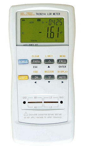

    New tool for me. So far i had only multimeter lookalike L meters with ranges 2mH to 20mH.
    But this one, the TH2821A, is somewhat more serious tool.
    It can measure L, C, R, Z and Q at coils.
    It can measure at 100Hz, 120Hz, 1kHz and 10kHz.
    So i was thinking to perform series of measurements on few coils that i already have.
    One coil is Detech 38x30cm (15x12") coil for MXT | MXT PRO / 300 | DFX / 300 |V3 V3i / Spectra | M6 models
    Another coil is Black Max coil which came with White's 6000 Pro Xl.
    Both original coils, both well known, both perfect for learning and mastering the new LCR meter.

    ...
    So i performed series of measurements. And i got somewhat confusing results at the end!?
    If i was not knew from before the real specs of those two coils; how could i tell which one of measured result is accurate?
    This is a question for everybody interested. Also a good situation for educational exercise.
    Ok... c'mon brainstormers! Let me hear you opinions!

    Here is the table with results:
    Attached Files

  • #2
    Are ANY other components connected to the coils during the measurement?

    What are the columns labeled "reminder"

    What is the "sef" coil? It is not mentioned in the pdf.

    What are the factory specs for the 2 coils mentioned in the pdf?

    What is the significance of the red numbers?

    Some of the readings are so off the wall as to indicate something is very wrong.

    Comment


    • #3
      The SEF should be close to the DFX numbers. The Black Max should be close to the Spectrum numbers.

      Ivica, this thing looks totally screwed up. Get a known discrete inductor and try that.

      Comment


      • #4
        Originally posted by Carl-NC View Post
        The SEF should be close to the DFX numbers. The Black Max should be close to the Spectrum numbers.

        Ivica, this thing looks totally screwed up. Get a known discrete inductor and try that.

        Yes i think so too.
        It seems LCR is faulty.


        Click image for larger version

Name:	100Hz.JPG
Views:	1
Size:	613.8 KB
ID:	347473
        Click image for larger version

Name:	120Hz.JPG
Views:	1
Size:	659.3 KB
ID:	347474
        Click image for larger version

Name:	1kHz.JPG
Views:	1
Size:	551.4 KB
ID:	347475
        Click image for larger version

Name:	10kHz.JPG
Views:	1
Size:	584.4 KB
ID:	347476

        Comment


        • #5
          Searched the Internet... apart from obscure manual; there is no schematic nor repair&servicing tips.
          There is a LCD sign "NG" displayed all the time. According to manual it means "No-Good" !??
          But nothing else explained on that.
          It is second hand, way long out of warranty.
          Therefore i am on my own
          ...
          ...
          Rickb; Carl already answered some of your questions.
          Red numbers are closest i got to what should i get.
          Reminders are original values (approximately) and serves there for comparison.
          ...
          However; there are some pretty interesting stuff mentioned in manual: http://www.pinsonne-elektronik.de/me...n%20Manual.pdf
          Calculations, formulas and rough algorithm.
          ...
          According to pretty messy results i got at different frequencies; it seems something in a calculation "chain" is pretty messed up.
          There are two processors on one pcb and a lot of "hardware" on another.
          Later on i might take few photos.

          P.S.
          C'mon... a "No-Good"!?? That explains a lot!
          Typically Chinese... "No-Good", end of a story!


          Comment


          • #6
            Originally posted by ivconic View Post

            C'mon... a "No-Good"!?? That explains a lot!
            Typically Chinese... "No-Good", end of a story!

            That's because "No-Good" is a literal translation of 不好 (bù hǎo).
            Perhaps it's actually an error message indicating a fault with the instrument, rather than a message related to the inductor.

            Comment


            • #7
              Originally posted by Qiaozhi View Post
              That's because "No-Good" is a literal translation of 不好 (bù hǎo).
              Perhaps it's actually an error message indicating a fault with the instrument, rather than a message related to the inductor.

              100% true.
              I knew that.
              But i am making fun of it because they didn't bother to make a list of possible faults.
              An "error code list" typical for such devices.
              Nor it can be found anywhere on the Internet.
              Maybe there is something on Chinese sites, but my browsers are not displaying anything.
              Nor i would understand if it was explained on Chinese.
              Chinese or not; this instrument would be very serious tool if it was not faulty
              ...

              Comment


              • #8
                A hardware...

                Click image for larger version

Name:	IMG_0355.JPG
Views:	1
Size:	959.1 KB
ID:	347477
                Click image for larger version

Name:	IMG_0354.JPG
Views:	1
Size:	921.9 KB
ID:	347478

                Ouch!

                Comment


                • #9
                  At least counting frequencies are pretty accurate, meaning further that uPc part seems to work correct.
                  Click image for larger version

Name:	IMG_0361.JPG
Views:	1
Size:	813.8 KB
ID:	347479
                  Click image for larger version

Name:	IMG_0360.JPG
Views:	1
Size:	579.3 KB
ID:	347480
                  Click image for larger version

Name:	IMG_0359.JPG
Views:	1
Size:	578.4 KB
ID:	347481
                  Click image for larger version

Name:	IMG_0358.JPG
Views:	1
Size:	919.9 KB
ID:	347482
                  Click image for larger version

Name:	IMG_0357.JPG
Views:	1
Size:	962.6 KB
ID:	347483
                  Most probably the fault is at "analogue" board. Lot of of cmos and opamps there.
                  There is also another thing; LCD contrast is weak.
                  And it dims a bit more when inductor is connected on socket.
                  Meaning further that something is wrong with power supply.
                  I checked rails; +5V and -5V are there, stable and correct.
                  3V3 also there, stable and correct.
                  What else...
                  Oh i wish i could use schematic now!

                  Comment


                  • #10
                    There is noticeable difference in LCD contrast with and without inductor in socket.
                    Observe the battery status symbol and how it changes contrast when i pull out the inductor from socket:


                    It must be related to power supply.

                    Comment

                    Working...
                    X