If this is your first visit, be sure to
check out the FAQ by clicking the
link above. You may have to register
before you can post: click the register link above to proceed. To start viewing messages,
select the forum that you want to visit from the selection below.
hi jo
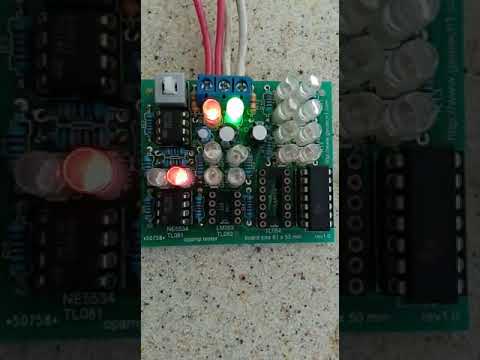
you see the video with 339 and do now want to trust of YOUR EYES??? LOL!
pin 12 connected via properties in CAD.
no mistakes. i always check all power ics' pins.
original schematic was just for opamps checking. i thought to add 339 because it used in md schematics.
you will see just half of LEDs lighten, because comparators are with 'open' output and there are not load resistors
but that's enough for the checking.
Hi kt315
The Video was not opening for me. I thought it was no longer available.
I managed to watch the video now.
I see this op LM2901 that the pinout is also different, equal to LM339.
I'm sorry if I didn't express myself correctly.
i do for geotechers. if they do not want to use it that is their problem. then why they ask what way to test opamps?
i sell last boards and will not return to this matter more. their unwillingness begets Unwillingness from my side to help. https://www.eevblog.com/forum/projec...rtain-op-amps/
for LM339 i added additional socket. i see LM2901 is same like LM339, one datasheet on both.
as the comparators are with 'open collectors' output you will see just one LEDs row flashing,
i did not set load resistors on outputs on board trying decrease pcb size to minimal possible. also, the checking of comparators are just an option,
but good option.
pleasure
Hi, how are you ? You could take a doubt, I saw in some assembly photos that you used the resistors R7 to R13 of 1k2 and the board uses 3k3. any reason for that?
Hi, how are you ? You could take a doubt, I saw in some assembly photos that you used the resistors R7 to R13 of 1k2 and the board uses 3k3. any reason for that?
Thanks
hello amigo
R7 to R13..... they are current-limited resistors for the LEDs. if you take power supply +-9V you choice one value, if +-15V you choice another value.
this is first issue. the reason is THE current you (YOU) choice. second. opamps output is limited on level 30mA, much datasheets do not mention this value but we take this. so 15-20mA through a LED is good and standart.
10mA is safe current level, for both opamps and LEDs. it gives us middle glow for un-bright/ordinary LEDs.
for example you have 3V LEDs bright. your source is +-15V. the voltage of opamp output is 15-1 = 14V. you choice 10mA current,
(14-3)/0.01 = 1.1kOhm.
Hello KT315. I put photos in fotoalbum in my profile and post for verification. On recommendation, I replaced the capacitors with 25V bought and delivered LM339N. https://www.geotech1.com/forums/album.php?albumid=129
I have not seen anything more useless and more stupid than your comparator tester!!!!
Probably the most trivial and most useless gadget in history of Electronics!!!
In Russia they say "durak's gadgetaya"!
 Tweet
Tweet


Comment