
 Tweet
Tweet
On the PCB "U2" looks like fake ic (with big Ti logo and wider pins). Probably lm4562 are real lm358. Try to check slew rate with generator and oscilloscope.
-
-
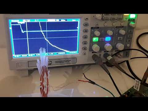
Slew rate is 6V/us. Should be 20.Originally posted by Vadim18 View Post
I think we got a winner.
TL072 measures 15V/us, as it should.Comment
-
Regardless of the fakes it doesn't seem to be an amplifier issue.
I've tried an LMH6622 dual opamp, 160MHz, 86V/us (verified on the scope) but I can't get below 40us for 200uV at the input (10mV at the output with 50 gain).
I'm starting to think that the high-voltage charge stored at the MOSFET's output capacitance, blocked by the diode, might be leaking into the input adding its own decay to the coil's decay.
I might try a different MOSFET/diode combination. Currently I'm using SPB17N80C3 (800V MOSFET) and UF4007 diode (1000V).Comment
-
Its worth a try ( swapping out the diodes ) ... also consider because your "analog ground" is moving around with respect to the power supply then the PSRR can come in to play ... its not crash hot on the LMH6622 .... Also this device is a voltage feed back amp and the frequency response drops off quickly as gain increases .... that can contribute to poor recovery.Originally posted by Teleno View PostComment
-
Originally posted by Vadim18 View Post
I would like to test the slew of some of my chips , is there a drawing of how to do this ? thanksComment
-
Just set the opamp up as a buffer and drive it with a square wave. Don't overdrive it, though.Originally posted by 6666 View PostComment
-
Originally posted by Carl-NC View Post
Thanks , can I drive the op amp with a 555 set at say 100Hz, there are plenty of theoretical circuits on google but they all only show a generator symbol not a real test circuit.Comment
-
The first suspect was the floating signal ground as you suggest. But it's actually quite steady, it stabilizes at 4us from the switch-off. That's far from the 40us delay I'm getting at the amp.Originally posted by moodz View Post
Top: gate signal.
Bottom: floating ground.
Next I disconnected the amplifier and just placed a 390 Ohm damping resistor across the coil as in this schematic:
The coil decay looks strange, not like an exponential. The reference is the signal ground, so any variations of this ground are cancelled.
The voltage at the node between the drain and the diode settles from 650V to 150V in 4us and then slowly drops. There's nothing funny between 4us and 40us, so it cannot be the cause.
I've tried adding parasitic caps and inductances to the circuit in LTSpice to try and duplicate the fenomenon but to no avail.
I have no clue as to what is going on!Comment
-
Well I figured out the problem.
This is the timing I got now. It has improved from 40us to about 10us
See the glitch on the lower right corner? That happens whe the charge at the drain, isolated by the diode, stabilizes.
I replaced the MOSFET by an IRF840. The problem was the original MOSFET had a too low capacitance! This caused a fast decay of the charge, especially at the beginning of the transient, that was feeding through to the damping resistor.
It is very important for early sampling that the charge at the drain be as stable as possible. A larger capacitance helps, a paradox. Probably it would be even better to use an external snubber.
The floating ground concept seems to work.Comment
-
Good detective work Teleno.
You just want the sig gen slew rate to be higher than the opamp slew rate you are trying to measure, by maybe 5x. BTW there are cheap DDS sig gens on eBay. I have an FY3200S and an FY8300S. Very useful.Originally posted by 6666 View PostComment
-
Update: after all it might have been the flux.Originally posted by Teleno View Post
The blocking diode I've used is SMD and as a result of my soldering attempts it was bathed in flux. Because of the high voltage involved and the carbon content through burning there's a very good chance it became conductive.
So I went to LTSpice and placed a 10K resistor across the diode and ... voila! the signal took more than 40us to decay to the 10mV level.
List of mistakes so I made (and corrected) in the course of this project:
- Ignoring the ESR of capacitors. Problem caused: ridiculous coil current, pulse frequency too high. Solution: low ESR electrolythics.
- Cheap fake op amps. Problem caused: lousy slew rates, time wasted in debugging. Solution: buy from reputable sources.
- Careless with soldering flux. Problem caused: carbon traces across high voltage component terminals, leaking currents into the signal path. Solution: use minimal flux and clean the PCB afterwards.
Lessons that had to be learned.
Not sure that the MOSFET/diode combination was causing the excessively long delay. However, a low capacitance, low leakage diode is essential because the purpose of the diode is to block the MOSFET's output capacitance during the falling part of the voltage transient. The high slew rate cuts through the diode's capacitance like knife through butter, so it's essential to select the diodes carefully. Most high-voltage, high current diodes will not block at all.
I found that for best results the diode must:
- have a voltage rating tightly adapted to the MOSFET's. Lower rating = less surface, less capacitance and smaller reverse current.
- have a current rating as far as possible below the coil's peak current (same effect as above). Actually just select them so that their max repetitive peak current value is close to the coil's peak current. After all PI is a pulsed current driver, take advantage of this.
- preferably be of the fast recovery kind.Comment
-
Nice troubleshooting and component guide lines.
I wouldn't have thought the flux would cause issues but with the high Voltage I can now see how it would.Comment
-
I have to take back the above statement.Originally posted by Teleno View Post
After removing all the flux remains I've soldered back the original components: SPB17N80C3 MOSFET, Logic_level 800V, 0.3ohm in series with a diode MURS160, 600V, SuperFast 50ns, 10pF. It works fine now.
A 90uH basket coil and a TLC082 as preamp gives the following trace:
This configuration is able to see my test gold nuggets of about 0.1 g.
Comment
-
The 90uH coil I'm using in my tests is peaking at 750V on 1A. It's a spiral basket coil 65cm in diameter.
Though it can detect my test gold nuggets at a distance equivalent to the diameter, the question is how to properly scale the coil so this design is usable in the fields.
Since a larger diameter requires less turns for the same inductance, the current will have to double or triple to maintain the same field intensity (ampere-turns) but then the peaking voltage will become impracticable.
It seems the most I can achieve is a pin-pointer to look for gold in rocks and cracks.
Regarding the op amps, I've tried LMH6622, LM4562, NE5532, TL072, TLC082 and NJM2068 with the last one being the winner with good slew rate, low noise and good recovery from saturation.Comment
-
In the video the coil looks very small.Originally posted by Teleno View Post
Is it really 65cm diameter (that's 25.6"), or did you mean 65mm?Comment
Comment