
 Tweet
Tweet
When making planar shields it's a good idea to include radial eddy breaks, and one of them needs to cross the entire shield (6-o'clock radial). Then you can attach the drain wire at the 12-o'clock position for balanced resistance.

-
-
The ferrite removes the symptom, but the source of the oscillation still exists.Originally posted by Teleno View PostComment
-
Thank you for the gif. This is the best planar shielding I have seen to date.Originally posted by Carl-NC View Post
The big question about shielding is: how much resistance is needed.
If the resistance is too low, the shield becomes too responsive. The eddy currents linger for a long time.
If the resistance is too high the EMI electric fields do not discharge fast enough.
I tried to generate a static electric charge of a few thousand Volt on the end of a PVC pipe, by rubbing it. Small pieces of styro foam or PVC foam would then stick to the pipe. Sometimes I could see or hear a spark when discharging the static. I figured that if I could see no reaction on the output of the detector when I touched the coil with the charged pipe, the shielding was good enough.
There are several problems with this method:
1) Just guessing the static voltage. No way to measure it.
2) When the humidity of the air is more than 50% it is difficult to obtain a good charge.
So just now I measured the conductivity of the static discharge mat on my workbench. I measure about 80K Ohm per 1 Inch. Maybe that could be a good number for the coil shield?
When I let the air humidity fall below 30%, I get sparks on my fingers. The static discharge mat and bracelet do an excellent job in protecting the circuits. A humidifier normally keeps the % above 50%, but sometimes I forget to fill the water.Comment
-
A screenshot.Originally posted by Teleno View Post
Thanks to all for the great insights that were shared and make this forum so great.Comment
-
The oscillation exists between the virtual ground and the floating ground. It peaks at 100 mV after the flyback and decays 4us later to 5mV.
I think it's related to this:
the transient when the ramp that defines the floating ground changes direction.Originally posted by Teleno View Post
Charles suggested touching the (-IN) of op amp U3, which has no effect, however doing the same to U6 does suppress the oscillation. U6 amplifies the ramp generated by the LT1117 current source and caps C2, C3 therefore any transient in the ramp is also amplified and fed to the THRESH input of the 555. I have to check what effects this may have.
It can also be a "feature" of the LT1117 when subject to sudden changes in the output voltage that tries to regulate, since it's an LDO nd these are rather unstable. I may replace it with a good old LM317 and see.
But at least and for practical purposes its effects can be suppressed with your idea, so I may try a prototype in the field.Comment
-
Totally by chance I did something that confirmed my suspicions.Originally posted by Teleno View Post
I attached a different 90uH coil and the signal was free from HF oscillation. The original coil was lying about on the same table and when I umintendedly it left it touching the smaller coil what I saw on the scope was this:
Then I confirmed the phenomenon placing the smaller coil on top of the larger one. Notice that the smaller coil is open circuit, there can be no currentt in it yet it makes the larger one oscillate like crazy.
So I guess this is why a ferrite bead on the coil cable helped, the coil itself is ths cause because of the stack of criss-crossing strides of wire. Don't do that. I could have made a basket coil with 7 radial slots and the strides would alternate sides naturally, but somehow I made 6 slots and had to skip one on every turn resulting in a second resonant mode.
The Darlington clamp works fine with the 90uH coil, no oscillation, it causes no feedback instability.Comment
-
As an alternative to the Darlington I've tried this JFET clamp with good results. The JFET acts a diode for negative inputs and as a switch positive, which reduces the amount of components.
The transfer curve of the clamped amplifier:
Notice that the output range for signals (positive input) is larger (1.1V) but low enough to avoid saturating the Op Amp.
The J113 adds about 35 Ohm to Rdamp when on, but there are inexpensive low Rdson versions like the J109 with 15 ohm. THe J108 is 8 ohms but expensive.Comment
-
One question regarding the shield of a planar coil.
Instead of messing with graphite sprays I wonder if conductive foam like the one used to pin ICs on wold be a suitable material. I've measured a sample I have and it's about 1k - 1k5 Ohm/cm resistivity uncompressed.
Would a coil sandwiched in this foam be EMI protected?Comment
-
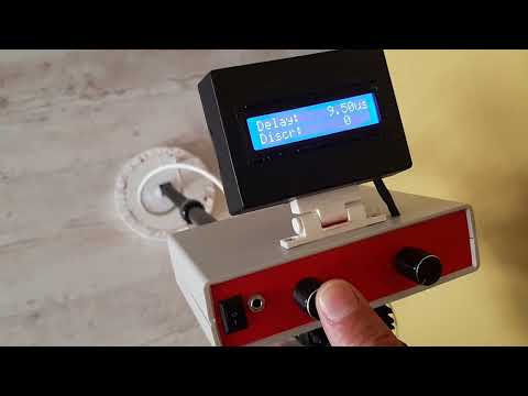
I've been working very hard on this project and finally I've got some results. I don't know how good they are but at least this PI can see some gold nuggets and gold chains at a distance of 9 - 10 cm.
I don't know how that compares with other PIs but you guys be free to judge.
The front end is the schematic in this thread. Then I've added an Atmega328P for signal processing. Basically oversampling/decimation (64 samples = 3 extra bits on top of the 10 bit ADC) and two low pass filters of different time constants, one with tau of 1024 samples for the background (baseline) and two filters with tau of 64 samples for target and EF. At 1000 Hz sampling rate it's 64 ms for the target (the time it takes to sweep 6.4 cm at 1m/s swing rate) and EF, and about one second for the baseline (one whole swing). The background is subtracted from (target - EF) and the resulting signal is passed to the sound function, a logarithmic VCO in software. There's a constant "tic tic" one second apart so the user knows the thing is working. A rotary encoder provides a menu, by now only the sampling delay can be modified. The coil is a flat construct sandwiched between two graphite coated polystyrene plates. Because of the shielding and the cable the original 2.5 us of the bare coil have ended up being 3.10 us earliest possible sampling delay.
The battery and LCD are still taped to the case but I'm working on that too. Sorry for the noisy kids in the background.

Comment
-
This is the provisional DipTrace schematic.
Comment
-
A word on the digital signal processing.
The sequence is EF sample, Tx pulse, Rx sample.
The processor waits for the EF sample to be ready, then measures the Tx pulse width and last takes the Rx sample. All samples are interrupt driven.
Each sample is stored in a ring buffer of length 64. The sum of the 64 samples is updated after each acquisition and then decimated (64 samples allow 3 bit resolution increase). The total resolution is 13 bits (10 by the ADC plus 3 by oversampling).
Next the current value Rx - EF is passed to two low pass filters, a fast one with a time constant of 64us and a slow one with a time constant of 1024 us. The difference of both filtered values is compared to an adjustable (noise)threshold and if larger it's sent to the audio subroutine (logarithmic voltage-to-frequency). This filtering provides for a slow ground tracking. A menu option allows for faster ground tracking (for heavy mineralized ground) by changing the time constant of the slow filter to 256 us. Some sensitivity is lost but partly compensated because the noise threshold can be set lower.
There's also a rather crude (yet) discrimination based on the changes in pulse width during the rise time of the Rx signal. This width is also oversampled and decimated for finer resolution.
A simple menu allows to set the delay, the threshold and the ground tracking mode.
When I have the time I'll publish the PCB and the code.
Comment
-
Nice work and thanks for posting!Comment
-
Now with "some" ferrous discrimination. It only works at shallow depths, so you still may have to dig but at least you won't have to sieve through the dirt trying to find the item.
Turn subtitles ON.
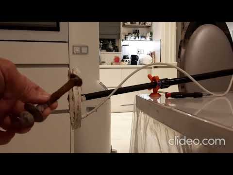
Since this PI is based on a relaxation oscillator around the transmit coil, an increase in the coil's inductance translates in a longer transmit period. The periods are counted and compared to a baseline, which is the latest count before a target signal overcomes the threshold.
In order to increase the resolution of the count, a ring buffer stores 64 consecutive periods increasing the resolution by 3 bits (oversampling/decimation principle). This value is then passed through a low-pass IIR filter with a time constant of 64 periods, adding another 3 bits to the resolution. The raw count is 12 bits, resulting in a final count of 18 bits. The ferrous threshold is set experimentally to 5 (3.5 bits), implying an accuracy of 14.5 bits.Comment
-
I wonder if a project book, a PCB, a kit etc would fly.Comment
-
Originally posted by Teleno View Post
I hope yes, Teleno!
I want encurage you for what is one of the best project I have seen this year on the forum!
Comment
Comment