Announcement

Collapse
No announcement yet.

FLC 100 -- unit conversion + meaning of noise

Collapse
X
 
  • Filter
  • Time
  • Show
Clear All
new posts

  • FLC 100 -- unit conversion + meaning of noise

    Hello. Hope you all are doing great. I have a pretty basic question that I am confused about for the unit conversion while using FLC 100 magnetometer. Datasheet (link) has following specifications:
    Specifications
    Meas. range +/-100uT, other ranges on request
    Output voltage OUT+ ref. to OUT− +/-1 V/50 uT, max. +/-2,5 V
    Reference output OUT− 2.5 V ref. to supply ground (0 V)
    Supply voltage 5 V +/- 5%


    • How do I convert the V to T for example?
      • It says 1V = 50uT, so is it just that?
      • So if I measure upto mV level accuracy with datalogger, does that mean simply mean I multiply 1mV value with 50 to get result in nanoTesla?


    • Why does it say max +/-2.5 V with max reading +/-100 uT?
      • Wouldn't that make it +2.5V = +100uT?
      • In that case, 5V total would correspond to 200uT total, implying 1V = 40uT, instead of 50uT?


    • The specification says "Accuracy at 20 ◦C +/-2% +/- 0.3 uT". What does that mean?
      • If I read let's say 75uT then error = +/-2% of 75uT +/- 0.3uT = +/- 1.5 uT +/-0.3 uT = +/- 1.8 uT
        • ie. my reading is somewhere between 73.2uT to 76.8uT?


    • The specification also says "Noise: <0.5 nT_RMS or 3 nT_PP (0.1 to 10 Hz), ∼150 pT/√ Hz @ 1 Hz". What does this mean?
      • If my measurement is done at 1Hz, noise in the data is ~150pT?
      • In that case, what is difference between Accuracy and Noise? Is there any literature I can refer to ?


    • What would a positive and negative reading mean? Which would be North and which would be South typically in magnetometer reading?


    I would appreciate answer to any question. Thank you in advance.

    PS: I don't know if this is right section to post or in Magnetometer section. I believe these are basic electronic questions as well. Moderator, please move it to another section if it doesn't fit here.

  • #2
    Good questions!
    I was confused the same in the past.
    Than i realized that they are messing up with too many false facts.
    By now i used FGM sensors.
    Up from recently i am working on my own sensor.
    Where i will exactly understand what is all about, since i am designing it.
    My sensor will give voltage and frequency at the outputs.
    I warmly suggest you the same; make your own sensor and establish your own rules.

    Comment


    • #3
      Meas. range +/-100uT,
      Total measuring range. Above, there is a curvature of U(H) characteristics increasing inaccuracy.
      Output voltage OUT+ ref. to OUT− +/-1 V/50 uT, max. +/-2,5 V
      1V=50uT;
      1mV=50nT; Such accuracy at ADC 10bit
      Reference output OUT− 2.5 V ref. to supply ground (0 V)
      2.5 V is level 0 uT
      3,5 V = +50 uT
      1,5 V = -50 uT
      2,501 V = +50 nT
      2,499 V = -50 nT
      4,5 V = +100 uT
      0,5 V = -100 uT
      Accuracy at 20 ◦C +/-2% +/- 0.3 uT". What does that mean?
      2 % of 50 uT is 1 uT but at the same time not more than 0,3 uT.
      2 % in low measuring ranges.
      This is a constant measurement error that changes at a temperature of 2 nT/K.
      "Noise: <0.5 nT_RMS or 3 nT_PP (0.1 to 10 Hz), ∼150 pT/√ Hz @ 1 Hz".
      Noise 0.5 nT, 150 pT is a dynamic value, irrelevant to you.
      This means that a measurement with an accuracy of 1 nT is actually worthless, that is my opinion.
      What would a positive and negative reading mean?
      Sensor in the W-E position you have 0 T.
      Position vertically up + 48 uT, vertically down - 48 uT (values in Europe).
      Best regards
      PS
      FGM sensors give several times better accuracy, of course it all depends on the rest of the measuring system.

      Comment


      • #4
        Originally posted by ivconic View Post
        Good questions!
        I was confused the same in the past.
        Than i realized that they are messing up with too many false facts.
        By now i used FGM sensors.
        Up from recently i am working on my own sensor.
        Where i will exactly understand what is all about, since i am designing it.
        My sensor will give voltage and frequency at the outputs.
        I warmly suggest you the same; make your own sensor and establish your own rules.
        Thank you for the reply.
        How much is the cost of FGM sensors? Is it the one in the link below?
        How did you make your own sensor? I would love to try that. I did see few documents online that wrapped two coils on iron core and see the signal with oscilloscope. However, I thought the main problem is how to do quality control with winding the wires. I thought the signal was really sensitive to drive and sense coil orientation?
        Do you have any documents or posts here or some links I can follow to see how you have done it? I would love to hear more.


        Originally posted by Krzysztof View Post
        T
        Best regards
        PS
        FGM sensors give several times better accuracy, of course it all depends on the rest of the measuring system.
        That is awesome reply. I really appreciate your answer. Thank you.
        Few questions:
        - Why would W-E position have 0T?
        - 150pT is dynamic value as in it depends on frequency? What frequency is that?
        - Measuring 1nT is not possible with this sensor, as 1mV would correspond to 50nT?
        - FGM as in this one (https://watson-gyro.com/product/magn...meter-fgm-301/)? Also, by any chance do you know how much they cost?


        Also, if I want to measure something in the range of 1nT (or may be more accurate), what would be the best sensor? Does fluxgate achieve that? I don't think/assume other types (such as SQUID or Proton...) are practical or cheap ones?

        I read few academic paper where medical devices use gradiometer of SQUID magnetometer for brain activity in order of pT or fT. Those definitely would be super expensive (and overkill) for many applications.

        Comment


        • #5
          1. Yes. N-S -> +20uT; S-N -> -20uT; (in Europe).
          2. Physics book or Wiki. 1Hz.
          3. Yes. Poor resolution.
          4. This one is similar. 1mV would correspond to 20nT, analog output.
          FGM+ from https://www.fgsensors.com/
          price about 35$, company from Slovenia. Digital output +/- 50uT -> 50 - 120 kHz. 1LSB resolution

          Comment


          • #6
            Still here, but the price of 60 Eu:
            https://magnetometer-kit.com/product/fgm-3-pro-magnetic-field-sensor/

            Only a company without an address, registered in Cyprus.

            Comment


            • #7
              Originally posted by Krzysztof View Post
              Still here, but the price of 60 Eu:
              https://magnetometer-kit.com/product/fgm-3-pro-magnetic-field-sensor/

              Only a company without an address, registered in Cyprus.
              Originally posted by Krzysztof View Post
              1. Yes. N-S -> +20uT; S-N -> -20uT; (in Europe).
              2. Physics book or Wiki. 1Hz.
              3. Yes. Poor resolution.
              4. This one is similar. 1mV would correspond to 20nT, analog output.
              FGM+ from https://www.fgsensors.com/
              price about 35$, company from Slovenia. Digital output +/- 50uT -> 50 - 120 kHz. 1LSB resolution

              Thank you Krzysztof.

              I remember I had bought few of fgsensors and their MAG arduino shield. I didn't realize they were more accurate than FLC-100. I always thought they were DIY type and FLC was more standard one. I remember FG3+ sensor gave results in frequency and I had to solder a circuit to get voltage output, and I lost that circuit before connecting and switched to FLC-100.

              By the way, FLC-100 has this extra pin -- http://md-ecs.com/wp-content/uploads...et_FLC-100.pdf -- called SYNC. How do I use it? I leave that pin unconnected. So I assume I am operating at 1Hz by default. Do I just connect it to some external PWM signal to increase frequency (and decrease noise)?

              Comment


              • #8
                Originally posted by sachindra View Post
                ...I remember FG3+ sensor gave results in frequency and I had to solder a circuit to get voltage output...
                Each type of non-linear conversion can introduce some lost and trade off.
                And it is tough (if not impossible in real world) to achieve linear conversion from FGM f output to voltage.
                So is better to directly measure the frequency.
                It is rock solid method, since you avoid ADC and directly engage digital inputs.
                It takes only to poll the pin with rising or falling edge of a signal that coming from FGM sensor.
                Everything else is History...

                Comment


                • #9
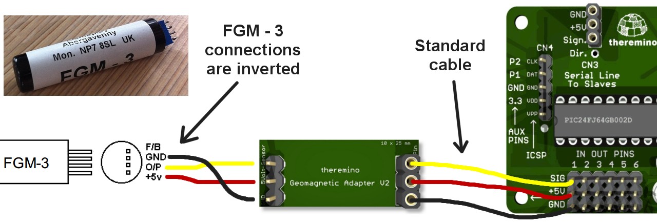
                  Theremino Geomagnetic Adapter + FLC100???

                  https://www.theremino.com/en/hardwar...eology-sensors

                  Is it possible to connect flc100 to Theremino Geomagnetic Adapter for better power stability?

                  Comment


                  • #10
                    Read previous posts.
                    FGM3 is a sensor with a digital output, the adapter changes its signal using the DAC to an analog form, the Theremino input again converts the signal using the ADC into a digital form necessary for processing by the PIC processor.
                    WHAT FOR?
                    You only introduce further nonlinear distortion of the signal. Connecting the FLC100 to the adapter will not do anything - you will not see any signal, because you connect the analog output of the FLC100 sensor to the digital input of the adapter.
                    The easiest way is to connect the FGM3 to the input of the T1 counter in ARDUINO and take care of further signal processing there. Even the older versions of the overlays from the fgsensors site are pretty decent.
                    In general, FGM3s are cheaper than FLC100.
                    Best regards Chris.

                    Comment


                    • #11
                      I have a question about the inductive flc 100 sensor, the coil is 550uh, and the impedance is 5.5ohm. What is the best frequency for it? How many khz should I get?

                      Comment


                      • #12
                        17кhz

                        Comment


                        • #13
                          A problem that it will not rise more than 14.7 khz , even if it is raised or lowered in a capacitive capacity, which is a problem

                          Comment


                          • #14
                            There, the core of the coil plays the biggest role, the other elements have (and should) have less influence on the frequency.
                            F=f(B(H)).​

                            Comment


                            • #15
                              B=f(u(H)).
                              F>frequency.
                              H>magnetic field strength.
                              B>magnetic flux density.
                              u>permeability of the coil core.
                              f>function.

                              Comment

                              Working...
                              X