Announcement

Collapse
No announcement yet.

Polarizeing current

Collapse
X
 
  • Filter
  • Time
  • Show
Clear All
new posts

  • Polarizeing current


    Hi all.


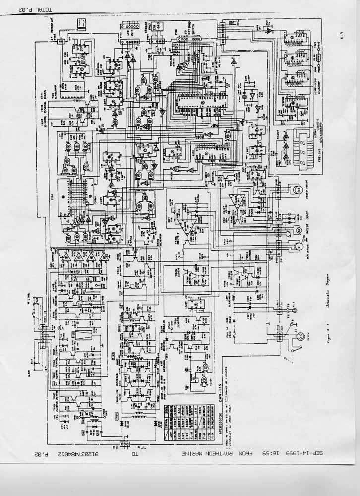
    Well, I was able to find a LM2904 in my junk circuit board inventory. It seems to have about the same spec as the LM358, at least it goes to ground. I put it together just as you said Carl, and it worked fine. Then I integrated it into the AD605 variable gain amp and with a little trouble, I got that to work. Analog”s applications bulletin on the AD605 uses caps for AC coupling on VGN and Vin, I removed them and it seemed to work better. Now that I have all that, I’m not sure where to put it, and GREG, I don’t need an answer from you If looking at the schematic gives any one an idea on where to incorporate this ramp let me know. I can send a high res copy to any one that wants it, just email me and I’ll send it right out. Even the high res is not all that good because it was faxed to me from Raytheon and there copy is about 4 generations old.


    Thanks,


    Tod


    [email protected]

  • #2
    Re: Try this...and I did

    Yikes! There's a lot of stuff in that schematic and not enough resolution. Could you mail me a good photocopy?

    Comment


    • #3
      Re: am I way Off base

      I am trying to make something similar for use in the north when doing ice rescue for people under ice. I was looking at about the same rpms, but I haven't been able to do much besides designs and searches for schematics for controlling the systems. I'll let you know if I find or design anything more.


      Chief

      Comment


      • #4
        Re: Which Proscan PI?

        hi dan
        just read your message about changes ill let you know how i got on shortly

        ian

        Comment


        • #5
          Re: Which Proscan PI?

          hi dan
          just read your message about changes ill let you know how i got on shortly

          ian

          Comment


          • #6
            Re: Which Proscan PI?

            hi dan
            just read your message about changes ill let you know how i got on shortly

            ian

            Comment


            • #7
              Re: GMVSAT

              Does the DD coil have 2 TX coils? Concentric coils usually have 2 TX coils but not sure why DD would.

              Basically you need to make sure the TX coil(s) has the same reactance (L-C) as the stock one. That's because most detectors use a Colpitts oscillator and the coil reactance sets the frequency. Then, you need to do the same on the RX coil because most receivers (on single frequency detectors) use a bandpass input tuned to the same frequency as the TX.

              It's kind of tough to calculate the inductance and capacitance of scramble-wound coils. There's some approximate equations out there (inc. one somewhere on my web site) but I don't know how good they are. So you may end up doing trial-and-error on making the individual coils. Once you get them about right, then you have to put them on a substrate and get the overlap just right.

              - Carl

              Comment


              • #8
                Re: GMVSAT

                Does the DD coil have 2 TX coils? Concentric coils usually have 2 TX coils but not sure why DD would.

                Basically you need to make sure the TX coil(s) has the same reactance (L-C) as the stock one. That's because most detectors use a Colpitts oscillator and the coil reactance sets the frequency. Then, you need to do the same on the RX coil because most receivers (on single frequency detectors) use a bandpass input tuned to the same frequency as the TX.

                It's kind of tough to calculate the inductance and capacitance of scramble-wound coils. There's some approximate equations out there (inc. one somewhere on my web site) but I don't know how good they are. So you may end up doing trial-and-error on making the individual coils. Once you get them about right, then you have to put them on a substrate and get the overlap just right.

                - Carl

                Comment


                • #9
                  Re: GMVSAT

                  Does the DD coil have 2 TX coils? Concentric coils usually have 2 TX coils but not sure why DD would.

                  Basically you need to make sure the TX coil(s) has the same reactance (L-C) as the stock one. That's because most detectors use a Colpitts oscillator and the coil reactance sets the frequency. Then, you need to do the same on the RX coil because most receivers (on single frequency detectors) use a bandpass input tuned to the same frequency as the TX.

                  It's kind of tough to calculate the inductance and capacitance of scramble-wound coils. There's some approximate equations out there (inc. one somewhere on my web site) but I don't know how good they are. So you may end up doing trial-and-error on making the individual coils. Once you get them about right, then you have to put them on a substrate and get the overlap just right.

                  - Carl

                  Comment


                  • #10
                    Re: Which Proscan PI?

                    Dan,

                    That's the best post in a long, long, time. Congratulations. Burning smells do nothing for anyone, huh!

                    Graeme

                    Comment


                    • #11
                      Re: Which Proscan PI?

                      Dan,

                      That's the best post in a long, long, time. Congratulations. Burning smells do nothing for anyone, huh!

                      Graeme

                      Comment


                      • #12
                        Re: Which Proscan PI?

                        Dan,

                        That's the best post in a long, long, time. Congratulations. Burning smells do nothing for anyone, huh!

                        Graeme

                        Comment


                        • #13
                          Re: GMVSAT

                          I would guess that both impedance and resonance are important, with the resonant freq. more so, esp. on matching the RX to the TX.

                          Ferinstance, let's say the GM has a Colpitts osc. and you design the TX coil a little bit off, so the TX freq. is 45kHz and not 50kHz. No big deal. Also, your resonant impedance is also off some, which means you may not get as much power transfer to the coil. Again, no big deal, TX power is just a little lower.

                          OK, now what's critical is to get the RX resonant freq. close to 45kHz. If you err to the high side, say 55kHz, then the received signal will be greatly attenuated, depending on the Q of the RX coil. But let's say you nail the RX resonance at 45kHz, but the resonant impedance is off. Like the TX coil, this might cause a little degradation in power transfer but as long as it's not WAY off you should be OK.

                          Comment


                          • #14
                            Re: GMVSAT

                            I would guess that both impedance and resonance are important, with the resonant freq. more so, esp. on matching the RX to the TX.

                            Ferinstance, let's say the GM has a Colpitts osc. and you design the TX coil a little bit off, so the TX freq. is 45kHz and not 50kHz. No big deal. Also, your resonant impedance is also off some, which means you may not get as much power transfer to the coil. Again, no big deal, TX power is just a little lower.

                            OK, now what's critical is to get the RX resonant freq. close to 45kHz. If you err to the high side, say 55kHz, then the received signal will be greatly attenuated, depending on the Q of the RX coil. But let's say you nail the RX resonance at 45kHz, but the resonant impedance is off. Like the TX coil, this might cause a little degradation in power transfer but as long as it's not WAY off you should be OK.

                            Comment


                            • #15
                              Re: GMVSAT

                              I would guess that both impedance and resonance are important, with the resonant freq. more so, esp. on matching the RX to the TX.

                              Ferinstance, let's say the GM has a Colpitts osc. and you design the TX coil a little bit off, so the TX freq. is 45kHz and not 50kHz. No big deal. Also, your resonant impedance is also off some, which means you may not get as much power transfer to the coil. Again, no big deal, TX power is just a little lower.

                              OK, now what's critical is to get the RX resonant freq. close to 45kHz. If you err to the high side, say 55kHz, then the received signal will be greatly attenuated, depending on the Q of the RX coil. But let's say you nail the RX resonance at 45kHz, but the resonant impedance is off. Like the TX coil, this might cause a little degradation in power transfer but as long as it's not WAY off you should be OK.

                              Comment

                              Working...
                              X