Announcement

Collapse
No announcement yet.

Whites TDI : Pots & switchs values/position

Collapse
X
 
  • Filter
  • Time
  • Show
Clear All
new posts

  • Whites TDI : Pots & switchs values/position

    Hi,

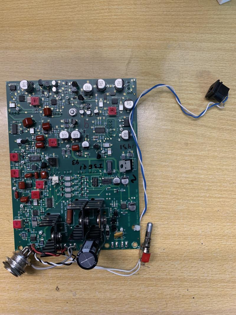
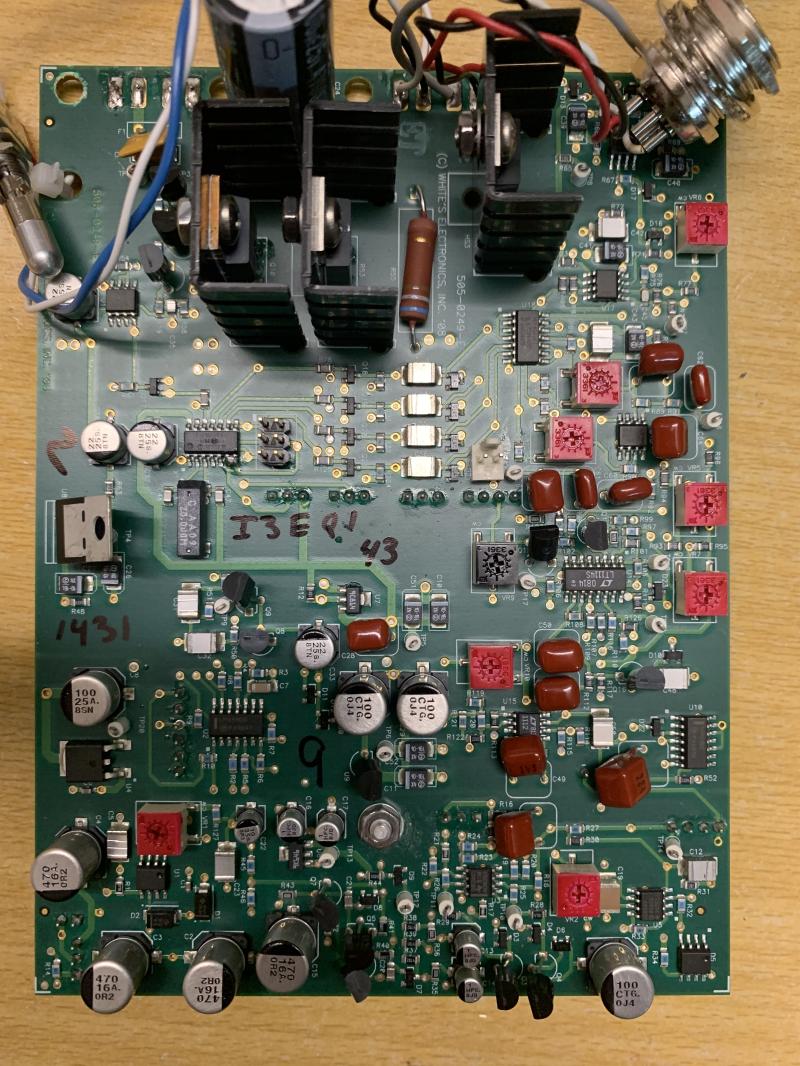
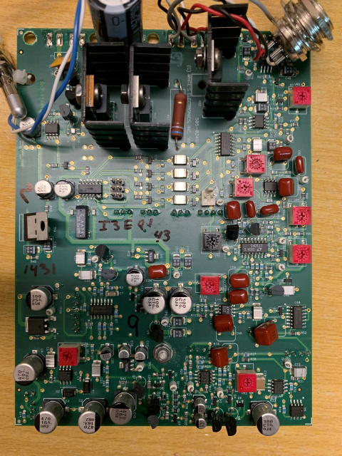
    Having just a TDI board and a coil, I would like to reassemble the detector complety.
    So I wanted to know what are the values ​​of the different potentiometers, if the switches are just on/off?
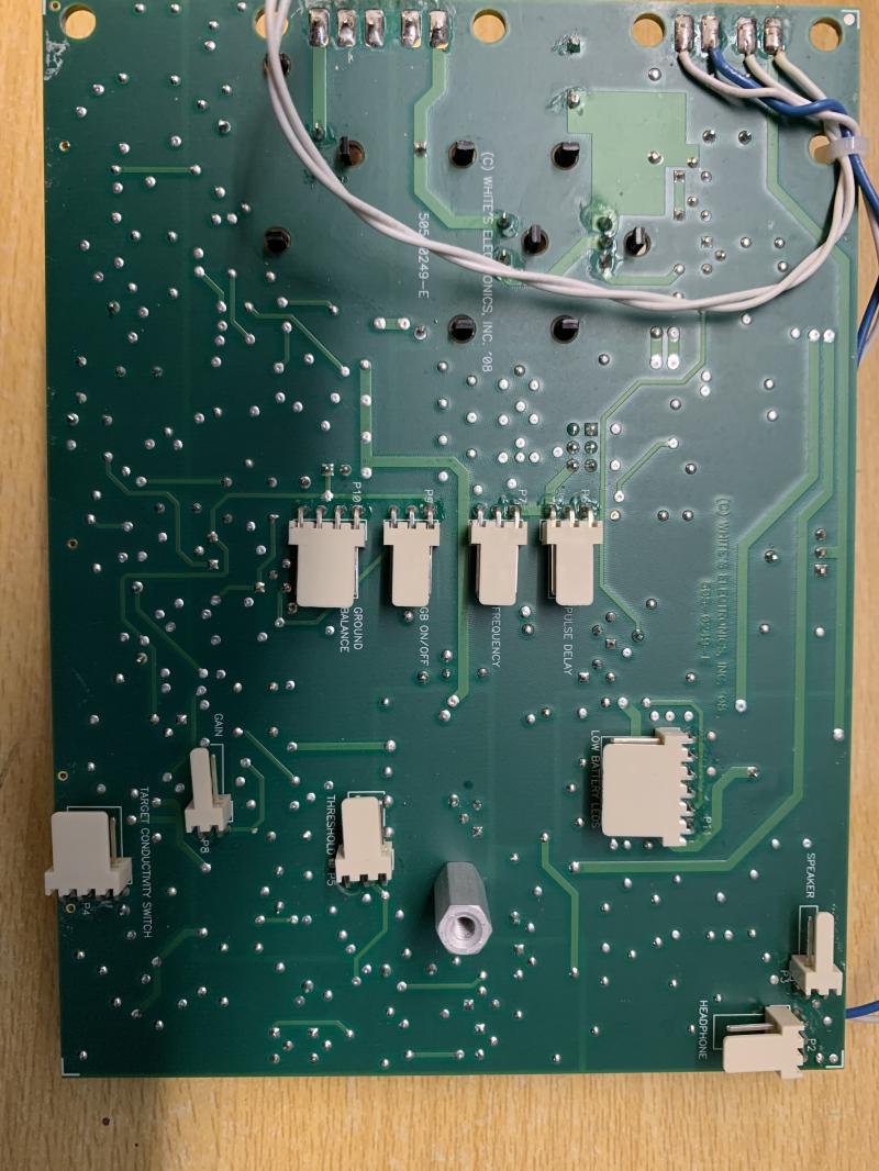
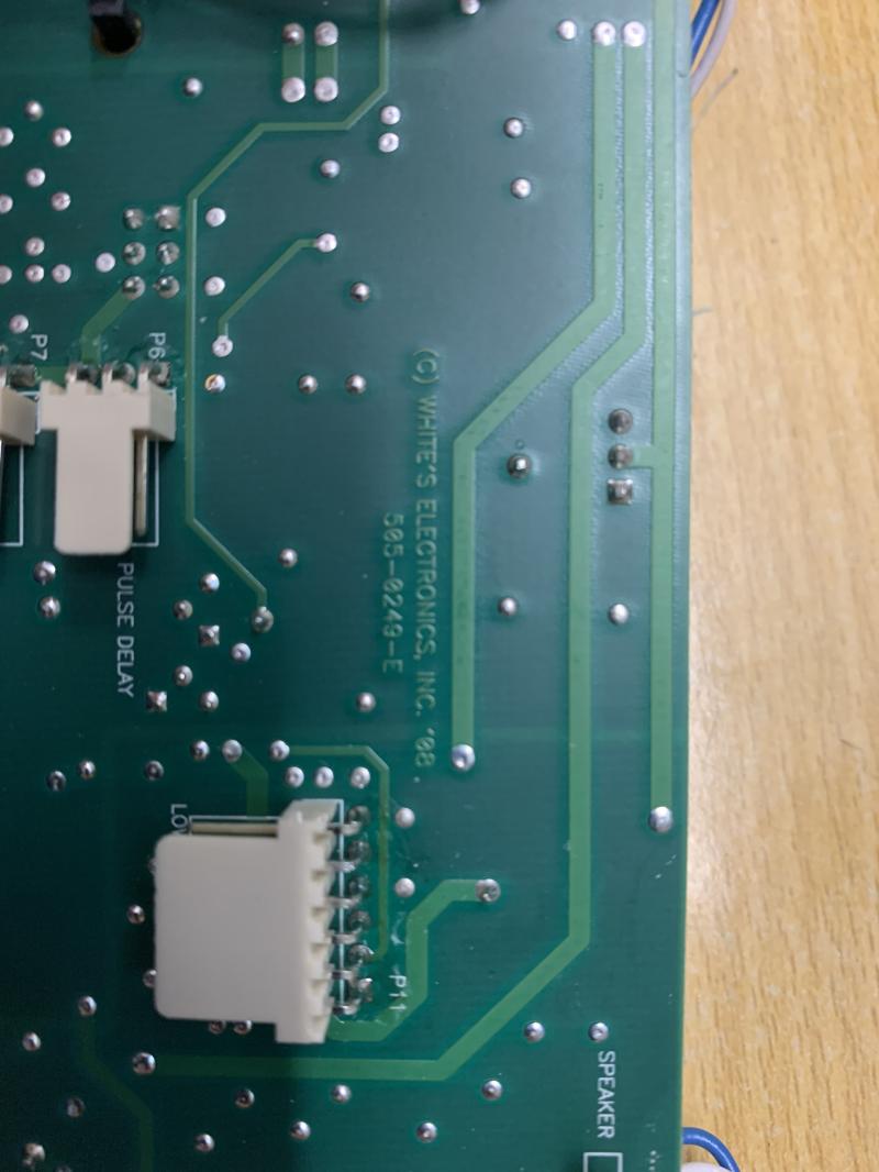
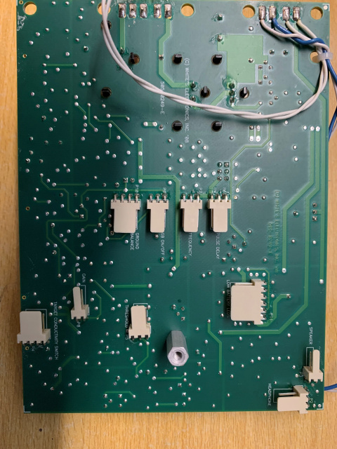
    And also photos to know where each conductor goes in the JST connector on the board and the potentiometers/switches?

    Thanks.

    David

  • #2
    Most of this is repeated from Steve's forum:

    Pulse delay & Frequency are 10k, although 100k will also work.
    Gain is 50k.
    Ground balance is 100k.
    Threshold is 100k.

    All pots are mono.

    As I recall the PCB is marked where everything plugs in. The pin connections are all linear, that is, outside-middle-outside on the pot (or switch) is the same on the connector. This means you will have to figure out which outside connection goes where but that's pretty easy once you fire up the circuit. If the pot operation is backwards, swap the outside pins. Sorry, I don't have a diagram or a pic.


    However, JST connectors (1.25mm) were used on the TDI-SL board, I don't recall they were ever used on the TDI board. They should be 0.1" pin connectors. Can you post a photo?

    Comment


    • #3
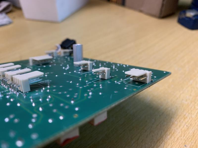
      Not JST, I think KF2510 Connector.

      The conductivity switch must be connected to an outlet with 4 pins connector (board).
      Does it go on a 3-pin or 6-pin OFF-ON-OFF switch?
      Because in the case of a 3-pin, do we connect the two pins in the middle of the connector to the same middle contact of the switch?


      Comment


      • #4
        I had forgotten, the Mode switch has some weird wiring. I think it's a DPDT-center-off (6 lugs) but I'll need to open up a TDI to see how it's wired.

        Comment


        • #5
          Originally posted by Carl-NC View Post
          I had forgotten, the Mode switch has some weird wiring. I think it's a DPDT-center-off (6 lugs) but I'll need to open up a TDI to see how it's wired.
          Ok thanks.
          What is the type of HP (Watts)? How to cable a volume potentiometer as on the TDI Pro on the Pulse Scan?

          Comment


          • #6
            Originally posted by Melano87 View Post
            Ok thanks.
            What is the type of HP (Watts)? How to cable a volume potentiometer as on the TDI Pro on the Pulse Scan?
            16ohms 0.3w

            Click image for larger version

Name:	tdi.JPG
Views:	1
Size:	209.1 KB
ID:	363385

            Comment


            • #7
              Originally posted by Rom_1 View Post
              16ohms 0.3w

              [ATTACH]57869[/ATTACH]
              Hi, many thanks ? Rom_1 ?.
              You seem to have a Pulse Scan.
              Is it possible to have photos of the switches and potentiometers, and also the white connectors of the potentiometers and switches on the turntable?

              Comment


              • #8
                Originally posted by Carl-NC View Post
                I had forgotten, the Mode switch has some weird wiring. I think it's a DPDT-center-off (6 lugs) but I'll need to open up a TDI to see how it's wired.
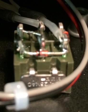
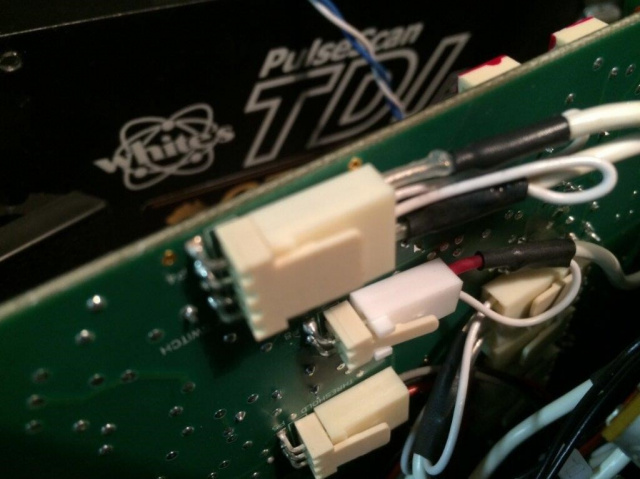
                I came across photos on another forum showing the wiring of connectors and switches on the Pulse Scan. (The photos are like this on the site, not of very good quality)
                Is the wiring of the conductivity switch just unlikely?
                I have the impression that on the white connector the two wires in the middle are connected via a zener diode (Threshold & Gain too...?) One on the wire on the right and one on the wire on the left... I don't understand anything.


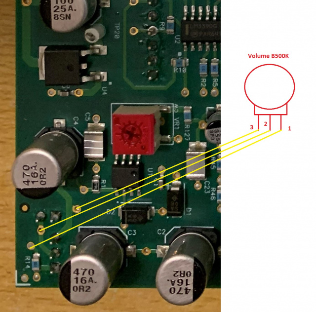
                Is it possible to mount a potentiometer for the volume like this?


                Comment


                • #9
                  It took me a while to recall the weirdness in the Mode switch but here it is:


                  The diodes are normal 1N4148 type, not zeners. The switch is what is weird, it is a DPDT "on-on-on" type. Here is the operation:

                  High: 1 & 2 are closed
                  All: 2 & 3 are closed (or maybe it's 1 & 4, it'll work either way)
                  Low: 3 & 4 are closed

                  There are 2 wires needed but the photo shows that both wires are shielded which is why the connector has 4 pins.

                  On the volume control, the trimpot VR1 is the volume control. You can remove it and replace with a control pot. Should be 5k.
                  Attached Files

                  Comment


                  • #10
                    Originally posted by Carl-NC View Post
                    It took me a while to recall the weirdness in the Mode switch but here it is:


                    The diodes are normal 1N4148 type, not zeners. The switch is what is weird, it is a DPDT "on-on-on" type. Here is the operation:

                    High: 1 & 2 are closed
                    All: 2 & 3 are closed (or maybe it's 1 & 4, it'll work either way)
                    Low: 3 & 4 are closed

                    There are 2 wires needed but the photo shows that both wires are shielded which is why the connector has 4 pins.

                    On the volume control, the trimpot VR1 is the volume control. You can remove it and replace with a control pot. Should be 5k.
                    Thanks once again.
                    It's Weird (laughs).
                    So the two internal wires of the "conductivity switch" connector are not to be wired, if I understand correctly.

                    For the Gain, how does it connect to the potentiometer because there are only 2 terminals (not 3) on the white connector?

                    The same goes for the Ground Balance, 4 terminals, the two wires in the middle are to be put on the same terminal in the middle of the associated potentiometer ?

                    And the ? GEB On-Off" which is originally a switch, we just have to connect the 3 terminals of the white connector to a potentiometer (keeping the central terminal in the middle at each end)?

                    Comment


                    • #11
                      So the two internal wires of the "conductivity switch" connector are not to be wired, if I understand correctly.

                      They are used for grounding the coax shields, this is for EMI suppression. You might get away with using a single twisted-pair connection to pins 1 & 4.

                      For the Gain, how does it connect to the potentiometer because there are only 2 terminals (not 3) on the white connector?

                      Connect to the middle lug and one of the outside lugs. If rotating the pot clockwise makes the gain decrease then you picked the wrong outside lug.

                      The same goes for the Ground Balance, 4 terminals, the two wires in the middle are to be put on the same terminal in the middle of the associated potentiometer ?

                      The GB pot connects as follows:

                      Pin1: outside lug of pot
                      Pin2: shield ground
                      Pin3: middle lug of pot
                      Pin4: shield ground

                      Again, try twisted pair to just pins 1 & 3.

                      And the ? GEB On-Off" which is originally a switch, we just have to connect the 3 terminals of the white connector to a potentiometer (keeping the central terminal in the middle at each end)?

                      No, you connect pins 1 & 2 of P9 to a switch that is part of the GB pot. You will also need to add a 100k resistor between P9 pins 2 & 3.

                      Comment


                      • #12
                        Originally posted by Carl-NC View Post
                        So the two internal wires of the "conductivity switch" connector are not to be wired, if I understand correctly.

                        They are used for grounding the coax shields, this is for EMI suppression. You might get away with using a single twisted-pair connection to pins 1 & 4.

                        For the Gain, how does it connect to the potentiometer because there are only 2 terminals (not 3) on the white connector?

                        Connect to the middle lug and one of the outside lugs. If rotating the pot clockwise makes the gain decrease then you picked the wrong outside lug.

                        The same goes for the Ground Balance, 4 terminals, the two wires in the middle are to be put on the same terminal in the middle of the associated potentiometer ?

                        The GB pot connects as follows:

                        Pin1: outside lug of pot
                        Pin2: shield ground
                        Pin3: middle lug of pot
                        Pin4: shield ground

                        Again, try twisted pair to just pins 1 & 3.

                        And the ? GEB On-Off" which is originally a switch, we just have to connect the 3 terminals of the white connector to a potentiometer (keeping the central terminal in the middle at each end)?

                        No, you connect pins 1 & 2 of P9 to a switch that is part of the GB pot. You will also need to add a 100k resistor between P9 pins 2 & 3.

                        Ok, for "Threshold", "Frequency", "Pulse Delay" pots and "Low battery" leds, no particular assembly ?
                        Thanks.

                        Comment


                        • #13
                          For Threshold, Frequency, and Delay pots connect the middle lug to the middle pin. The outer lugs can be connected backwards but you will know it when you turn the knob. LED also has polarity; it works one way and doesn't work the other way.

                          Comment


                          • #14
                            Melano are you some kind of joker?

                            Comment


                            • #15
                              Originally posted by Orbit View Post
                              Melano are you some kind of joker?
                              No, I don't understand what makes you think that.
                              Maybe my questions are redundant and my "electronic" level is probably lower than you.
                              I do what I can to redo this detector.

                              Thanks again to Carl for his patience and help.

                              Comment

                              Working...
                              X