Announcement

Collapse
No announcement yet.

Whites TDI : Pots & switchs values/position

Collapse
X
 
  • Filter
  • Time
  • Show
Clear All
new posts

  • #16
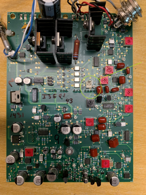
    good luck, i would not "tweak" any of those red pots on the board.
    it doesn't look like they have been moved which is good, if they are "factory" all your work is mechanical assembly.
    having to "setup" the machine may be a stretch for you going by your questions, if you want to modify the TDI thats great but i would wait until you have it functioning properly.
    modifying a working unit is easier than doing a non working one simply because you could introduce faults, if it works and you tweak something and stops functioning then your mod caused it, so reversing the mod should put it right.

    Comment


    • #17
      Originally posted by sinclairuser View Post
      good luck, i would not "tweak" any of those red pots on the board.
      it doesn't look like they have been moved which is good, if they are "factory" all your work is mechanical assembly.
      having to "setup" the machine may be a stretch for you going by your questions, if you want to modify the TDI thats great but i would wait until you have it functioning properly.
      modifying a working unit is easier than doing a non working one simply because you could introduce faults, if it works and you tweak something and stops functioning then your mod caused it, so reversing the mod should put it right.
      Hi, thanks.
      Yes, I was able to pick up this new card at a low price, never served at a Whites retail store in France.
      Having a coil, I wanted to reassemble it as factory, I just have to find a case now.
      Even if I had tinkered with the TDI SL, Tesoro, Sovereign I didn't want to do bull**** with this Pulse Scan. The explanations cannot be found on the Internet. I won't touch anything else on the card.

      Comment


      • #18
        Originally posted by Melano87
        I don't understand one of your sentences/answers "No, you connect pins 1 & 2 of P9 to a switch that is part of the GB pot. You will also need to add a 100k resistor between P9 pins 2 & 3. ?.

        On the "TDI Pulse Scan" it is normally just a switch, on the "TDI Pro" it is a GB Fine On-Off potentiometer, I would like to do on my Pulse Scan plate as on the TDI Pro.
        If we connect as you say the On-Off of the 10k potentiometer, and put this resistance of 100k. What are the remaining ? legs ? of the 10k potentiometer for?

        In addition, I saw a white connector on the other side of the board, what is it for?
        You want to get a potentiometer that has a built-in on/off switch. It will have the usual 3 lugs for the pot, plus 2 extra lugs (usually on the back) for the switch:


        Pot switches are mostly limited to SPST-type and the GB switch in the TDI is a SPDT-type. To make the SPST work properly you will need to add a 100k resistor, like this:


        Then 2 of the 3 pot legs are used for the GB pot. The third pot leg is not used.

        I don't know what connector (on the other side) you are referring to.
        Attached Files

        Comment


        • #19
          Hi Carl,

          Thanks, I understood that, sorry I may have misspoken.
          The part I don't understand is the wiring of the 10k part (not On-Off). Because on the white connector P10 (4 pins) of the Ground Balance I will come to connect my 100K potentiometer to it.
          But how do I also connect the 10k to it if I understand correctly?

          The connector I am talking about is the one on the other side, it is located above the P10 GB connector, is it related to the 10K GB Fine ?


          Thanks.

          Comment


          • #20
            Here is the wring for the normal GB and the coarse/fine GB:


            You might be able to get away with a single twisted pair instead of dual coax. If so, pins 2 & 4 will not be connected.

            I think the connector on the component side has to do with factory calibration, but I don't remember what was plugged in.
            Attached Files

            Comment


            • #21
              Ok, many thanks.

              Comment


              • #22
                The connection of the 6.35 female jack to the P2 connector, each pin of the connector corresponds to each "section" of the jack, or is there a particular assembly?

                Comment


                • #23
                  Like this:

                  Attached Files

                  Comment


                  • #24
                    Thanks again Carl.

                    Comment


                    • #25
                      Originally posted by Carl-NC View Post
                      Like this:

                      Hi Carl,

                      I had to leave aside my assembly for personal reasons and I was finally able to resume it, everything seemed to work, I had made a bad assembly on the conductivity switch but I was able to change it.
                      However, I will have to do tests.

                      I still have one last problem with the sound.
                      There is no sound in the speaker, to have sound I have to plug in a headset and I end up with sound in the headphones and the speaker. Why ?

                      Thanks.

                      Comment


                      • #26
                        It looks like your headphone jack is not wired properly. In my diagram above, "Pin 3" is the "tip" connection on the jack. "Pin 2" should connect to the pin on the opposite side of the jack so that when the headphone is unplugged it makes contact.

                        Comment


                        • #27
                          Originally posted by Carl-NC View Post
                          It looks like your headphone jack is not wired properly. In my diagram above, "Pin 3" is the "tip" connection on the jack. "Pin 2" should connect to the pin on the opposite side of the jack so that when the headphone is unplugged it makes contact.
                          Good evening Carl, it's okay, it works. All I need now is to do tests. Thank you again.

                          Comment


                          • #28
                            Looks like we bought the PCB TDI from the same store. I also had to make a box for the device.​ Click image for larger version

Name:	1.jpg
Views:	252
Size:	345.6 KB
ID:	408240
                            Attached Files

                            Comment


                            • #29
                              Originally posted by Orbit View Post
                              Looks like we bought the PCB TDI from the same store. I also had to make a box for the device.​ Click image for larger version

Name:	1.jpg
Views:	252
Size:	345.6 KB
ID:	408240
                              My case is made of aluminum and separates into 4 parts, your realisation is much prettier.

                              I think I have a problem but I can't figure out where. With the original 12" Dual Field, I capture Gain at full, no GB, Pulse Delay at the mini, Audible Threshold, Conductivity on All, a 19 cm gold ring (4-5cm less than a real TDI SL I was lent). For a one euro coin, the TDI SL took it at 30cm, my TDI modified at 2 cm (not 20 but 2)...........

                              Comment


                              • #30
                                Originally posted by Melano87 View Post

                                My case is made of aluminum and separates into 4 parts, your realisation is much prettier.

                                I think I have a problem but I can't figure out where. With the original 12" Dual Field, I capture Gain at full, no GB, Pulse Delay at the mini, Audible Threshold, Conductivity on All, a 19 cm gold ring (4-5cm less than a real TDI SL I was lent). For a one euro coin, the TDI SL took it at 30cm, my TDI modified at 2 cm (not 20 but 2)...........
                                pay attention to the gain potentiometer​ !

                                Comment

                                Working...
                                X