Announcement

Collapse
No announcement yet.

Partial digital PI design

Collapse
X
 
  • Filter
  • Time
  • Show
Clear All
new posts

  • #16
    Re: Partial digital PI design
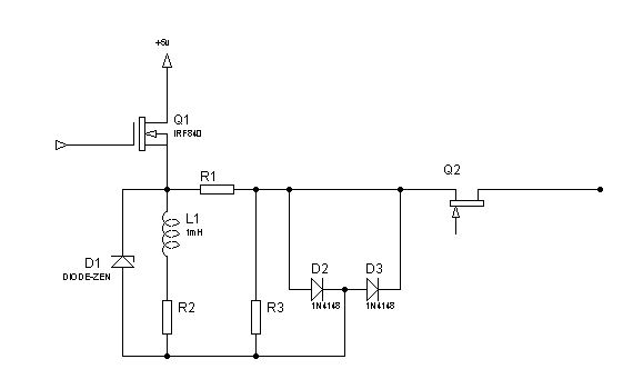


    if you useing just 5v

    hum less than a diode drop


    perhaps using a nchannel is best at lower voltages and to use the clamp accross the coil this makes a nice spring shock absorber affair
    you can rotary
    pulse

    also perhaps a transistor {scr } is a better choice of switch than a fet? ???? what do you think

    i like the dinky pcb size 80mmm by 20 wow

    nice

    a nice scr is buz devices i think

    these are fast at

    Comment


    • #17
      Re: Partial digital PI design

      here is a standard power scr
      normaly fount in a good old washing machine tuble dryer etc

      high voltage fast to220 but you can use a similar smd device also made by the same company smd version of this link


      maybe a good solution offers fast trigger and reset from just one driver transistor

      and is easy to reset fast...... offereing huge piv rating so the damper diode may be dispenced with

      a nice idea to try and see what sort of pulse decay etc you get
      in a sim first ....


      Click Here

      Comment


      • #18
        Re: Partial digital PI design

        hum noise yes this could be a problem

        the best way i think you have found is some sort of stop filter... perhaps a little smd choke {ferite block } on each pin

        here is a good ferrite site

        they will deal direct small orders also

        ecorecorp i used them before
        they are extreamly high quality and fast service
        and will also provide a make to spec.... service for a little cost...

        i think you need to separate the supply rails to the fet stage using a choke like a small ferrite beed and a decoupling cap 1nf -47nf at the non fet side of the choke
        {for smd} a square sleave on the center pin of the fet aswell {if you still plan to use a fet}

        place decopling for its power rail caps etc as close the the uc as possible

        and use 220 R res in series with any data i/o a/d d/a drive pins to limit the current {this will reduce also the noise from any pins} noise in micros means they are working hard and not efficiently or as efficienty }
        remembering to take into account this for any r/c calculation for pot's for any a/d or d/a used


        and use copper foil over the cpu section just trailing i/o to the fet {or drive stages} with a ground plane under side {or above}


        using groundplanes on these boards
        at HF the rule are VCC VPP TOP coppers
        with gnd plane and any drive pins then VSS fill then vss fill the underside also

        so all the power runs on a gnd plane


        appart from this noise may still be an issue so some sort of low pass of band stop filter {to take out the upper shelf about 15K could be cool also}
        but a ferrite will get rid of most of it
        it you choose a 1 mhz value then anything above will go....


        Click Here

        Comment


        • #19
          Re: Update


          hi robert and all

          after some concideration i decided to modify the front end slightly of my own design

          here is the modification i carried out on the multi fet tap coil drivers


          i also decided auto blanking is better

          incase you run over a mains supply and the switching goes funny and it missfires

          so i used a low tension transistor {100 v or so is ok here} and a few load resistors and an oa 90 to recify of some bias that can then be tweaked for best blanking level using a meter or scope to set the pot

          i also decided that differental ampilifcation can be switched with standard single end
          on both taps {per coil} so both types of amps in the one just switched filter and feedback would be realy cool

          i invite comments....

          and points

          dont worry about componet vaules too much just the layout that is of interest here

          Comment

          Working...
          X