Announcement

Collapse
No announcement yet.

IB Rx coil at Tx off

Collapse
X
 
  • Filter
  • Time
  • Show
Clear All
new posts

  • Been thinking what I would need to change to detect #9 shot with a 8inch coil. Charted decay curve for #9 shot(TC=.68us) and ground with a -1 and -1.3 decay slope. Now I'm wondering what would be the best timings to GB.

    I see the start amplitude for the #9 shot isn't correct, think the slope is correct. Think it should be start amplitude at zero time.
    Attached Files
    Last edited by green; 08-28-2020, 07:16 PM. Reason: added sentence

    Comment


    • Originally posted by green View Post
      Today I made tests with a #9 lead shot. I tried with pulses every 30us, then 25us then 20us then 15us. That is, one TX flyback every 15us. This worked best, but I only got 18mm distance from the 200mm concentric coil. I have seen way better than that, so the latest changes to the circuit obviously are not good. from reply #145

      Any thoughts why you got more distance before? Sampling #9 lead shot with a TC of .68us 1.5us sooner should increase the signal 10 times, maybe 90mm increase in detection depth with 200mm coil(hadn't noticed you were using a concentric coil, should make it easier to detect the shot but wouldn't get as large of increase in detection distance with 10 times the signal). What else could increase detection depth?

      Sampling faster should decrease the noise. Is there a formula for expected decrease in noise? Did sampling faster make much difference for you?
      A narrow sampling window increases the noise.
      Widening the sampling window integrates or averages the high frequency noise.
      Somewhere between there is the golden spot, where thee SNR is best.
      I keep finding the golden spot and loosing it. There are so many factors influencing the result and my capability is not great.
      For example: yesterday, I tried matching the capacitors on the positive and negative signal path, for the high pass and low pass filters. I matched 2 capacitors (1206) and soldered them on the board. Then I measured in circuit. The difference in the size of the solder blob, increased the capacitance of the one capacitor by 100pf. This causes a phase shift of this signal compared to the other signal. the phase shift translates into noise when subtracting the channels.

      Comment


      • I tested some chip capacitors awhile back. Can't find the test. What I remember. Capacitance changed the first time I tinned the ends, tinning again caused little change. If I were going to match chip capacitors I would tin the ends before trying to match them.

        Comment


        • Originally posted by green View Post
          I tested some chip capacitors awhile back. Can't find the test. What I remember. Capacitance changed the first time I tinned the ends, tinning again caused little change. If I were going to match chip capacitors I would tin the ends before trying to match them.
          Thank you for the feedback. I will try that.

          Comment


          • Originally posted by green View Post
            I tested some chip capacitors awhile back. Can't find the test. What I remember. Capacitance changed the first time I tinned the ends, tinning again caused little change. If I were going to match chip capacitors I would tin the ends before trying to match them.

            Interesting, I had not thought of that. In metal detector manufacturing matched caps are usually thru-hole. But new designs are beginning to use matched SMT caps.

            Comment


            • Originally posted by Carl-NC View Post
              Interesting, I had not thought of that. In metal detector manufacturing matched caps are usually thru-hole. But new designs are beginning to use matched SMT caps.
              Still haven't found my test data. Sure X7R caps changed the first time tinned. Think I tried some NPO's, don't remember if they changed. Maybe someone could try and see what they get.

              Didn't find where I posted before. Did find the data. Looks like NPO didn't change. Just one value, one manufacture. Would be interested in what others get. I would try some other values.
              Attached Files
              Last edited by green; 08-29-2020, 07:47 PM. Reason: added sentence

              Comment


              • Originally posted by green View Post
                Still haven't found my test data. Sure X7R caps changed the first time tinned. Think I tried some NPO's, don't remember if they changed. Maybe someone could try and see what they get.

                Didn't find where I posted before. Did find the data. Looks like NPO didn't change. Just one value, one manufacture. Would be interested in what others get. I would try some other values.
                Did you do these capacitance measurements immediately after tinning? If so, the change may simply be due to the temperature coefficient of the capacitor.
                Have a look at this document -> https://forum.digikey.com/t/understa...efficients/727

                If you want stability you should be using Class 1 capacitors. Class 2 types have a positive temperature coefficient that means capacitance increases with temperature. As an example, an XR7 Class 2 capacitor will operate from -55 degrees to +125 degrees C with a capacitance variation of +/- 15 percent. From your chart a 100nF XR7 increased from 93.9nF to 104.9nF after tinning. An increase of 11.7 percent.

                Just a thought ...

                Comment


                • Originally posted by Qiaozhi View Post
                  Did you do these capacitance measurements immediately after tinning? If so, the change may simply be due to the temperature coefficient of the capacitor.
                  Have a look at this document -> https://forum.digikey.com/t/understa...efficients/727

                  If you want stability you should be using Class 1 capacitors. Class 2 types have a positive temperature coefficient that means capacitance increases with temperature. As an example, an XR7 Class 2 capacitor will operate from -55 degrees to +125 degrees C with a capacitance variation of +/- 15 percent. From your chart a 100nF XR7 increased from 93.9nF to 104.9nF after tinning. An increase of 11.7 percent.

                  Just a thought ...
                  Tried two more 100nf X7R caps this morning. (.1X7R 50V 0603)not tinned 97.6n, first tin 104n, second tin 103.7n. (.1X7R 50V 0805)not tinned 94.4n, first tin 104.6n, second tin 104.8n. Waited a few minutes after tinning to measure. They are X7R that I have been using for bypass and coupling only(probably doesn't matter if the X7R's change when soldered). Hadn't used surface mount before playing with the metal detector. Purchased some different value X7R and NPO caps for stock when I started. Didn't know I could get some smaller than I could see. If I had been smarter I wouldn't have purchased the X7R caps and would have gotten sizes easier to work with.

                  Comment


                  • I use MMK5 radial poly caps for integrators and coupling. Tested 100nF 63V ones that I use. Start at room temperature new out of the box 100.7nF. Tinned on both leads with 350deg.C iron while connected to test meter. Value rose to 101.9nF. Left to cool for 10mins while still connected to test meter and value had fallen to 98.8nF. After 3 hours 98.9nF. No drift seen in test meter which is mains powered off wall plug psu.

                    Eric.

                    Comment


                    • Temperature sensitivity is only one of the problems ... alot of ceramic caps are also susceptible to microphonics

                      https://e2e.ti.com/blogs_/archives/b/precisionhub/archive/2014/12/23/stress-induced-outbursts-microphonics-in-ceramic-capacitors-part-2


                      not only that but they can also exhibit non-linearity ( ie capacitance varies with applied voltage ) ...

                      ..magnetic fields response ( last thing you want most times in a metal detector )

                      I have seen very bad amplifier effects in the front end due to these caps even in chip decoupling. ( ie not in signal path. )..

                      moodz

                      Comment


                      • Originally posted by moodz View Post

                        Temperature sensitivity is only one of the problems ...

                        moodz
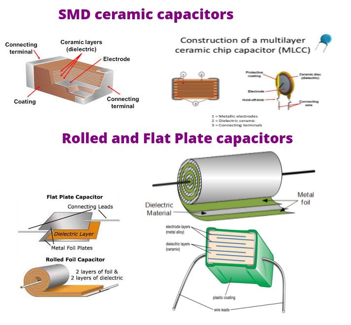
                        What about electric, EM and mechanical behavior of SMD chip ceramic capacitors?

                        And what about other sort of construction and build capacitors and their behavior?

                        At the end what is best / safe to select in MD modules build?


                        Comment


                        • Engineering is all about compromise.

                          Comment


                          • Its about specification ... no compromise if you specify C0G ( NP0 ) caps for critical signal paths. ;-)

                            Comment


                            • Some basic on multi-layer Ceramic capacitors and what all those letters mean:

                              https://ec.kemet.com/blog/mlcc-dielectric-differences/

                              Comment


                              • Ok i tried tinning some MLCC 1206 COG caps,4x33nf and 2 100nf,each 100nf cap was from a different batch.With the 33nf caps there was no change in capacitance after tinning,with the 100nf caps they changed there value after tinning by about 10 to 20pf.
                                I use the 33nf MLCC caps in a differential integrator cct and so i need to match them,but im still on the fence as to whether MLCC caps are better or PP thru hole caps are the way to go.

                                Comment

                                Working...
                                X