Announcement
Collapse
No announcement yet.
Delta Pulse
Collapse
X
-
i want to remind again simple thing. if you plan to use DP with 40us minimal DELAY WIDTH, as in original schematic,
you do not need to tune overdamping resistor. i reminder that in original schematic resistor value is 2k2. its enought.
Comment
-
correct is clear delta pulse (not name of the detector), clipped (by diodes on input of preamp) and inverted (be cause preamp inverts the signal). 2 diagram is correct.Originally posted by aaksts86 View Posthallo .. i have one question .. which diagram it correct in tp3 ...[ATTACH]38996[/ATTACH]
Comment
-
Hello Anatoli today mount the detector completely.STTH1210D is hot. IRF740 is in bright red. It detects nothing. No other components are hot the two diodes are lit.
---
hello. begin from checking of power supply, +E, -E. desolder STTH1210D - you must set it ONLY if you get
all working and detecting. close pins' pads of it by jump wire on board.
in test point T3 you have to see Square Pulses that run the MOSFET to open and close, like a switch.
and yes, now in your trouble you need the o-scope...
also, i noticed much that you CAN NOT use huge coil (1m x1m) in your room be cause very much armature
and electric nets around that do absolutely impossibility to check. schematic will be hyperoverloading.
Comment
-
One question to KT315.
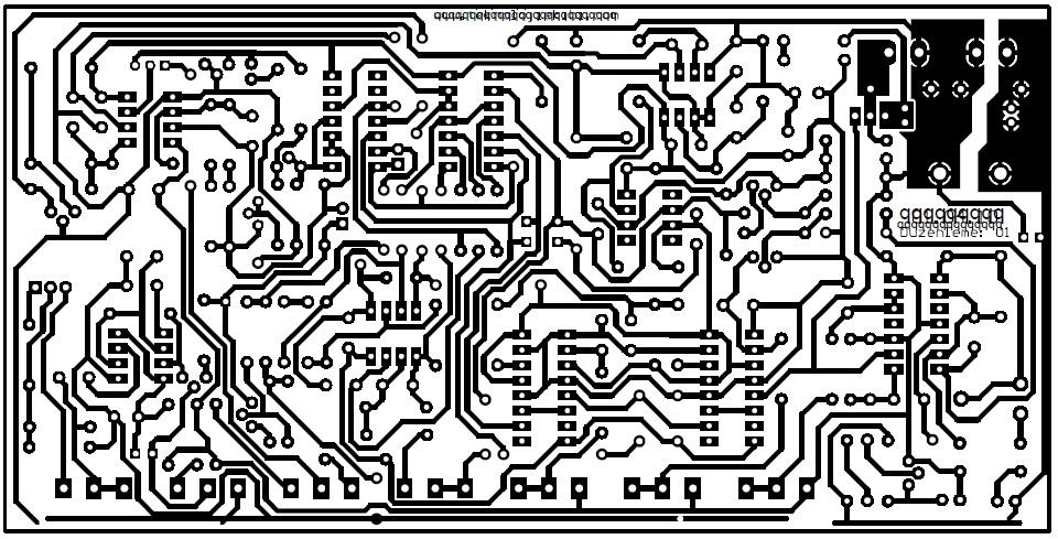
I watch the scheme (12/05/2016) in the lower left corner. Than I look at the last board rev2 in the lower left corner.
On scheme with two NPN transistors a module is designed to indicate the presence of power and the battery is depleted. The emitters of the two transistors are connected to the LEDs.
On board the transistors are connected to the LEDs with their collectors. It is marked on the board.
The question is where is the mistake?
I apologize if this question has already been asked and I missed the answer.
Comment
-
you are smoky RIGHT, Toros! thank you! its mistake (((
you found a cause why this part did not work. (while it worked nice at my first DP, alien's PCB was, but i did it on breadboard)
http://ipic.su/img/img7/fs/Bezimeni-2.1489346283.jpg
issue. or to use 2N3904 mirrored setted either BC237 BC546 BC547 BC548 etc. CBE pinout type.
Comment
-
Second question KT315.
To supply with what battery is calculated module, which mentioned above - with lithium ion batteries, nickel metal hydride or lead acid battery. I ask because the subject of the elements red diode lights up at 7.9 volts. Then the green LED turns off.
If we change R53 from 16k and do it 10,5k, then red diode Highlights in at 10.6 volts, which is normal, if use lead-acid battery.
Comment
-
hI for all I have a problem with my Delta Plus2 (snifer xr-71)is when i tested on the ground gives a sound as if he found a metal interrupted for a few second and then sound returns again and so on. i tried to set but in vain .my coi lis=42cm diameter.0.5awg.resistance=3ohm .frequency =130hz .please can you help me to solve this problem .Thank you in advance
Comment


Comment