
 Tweet
Tweet
Hey, anyone can help me, delta I no sound, unable to detect metal, LF357 output signal, 556 foot ninth pulse output, 4538 tenth foot no pulse output. When I touch T5E pole can be gained when the short sound, when I desoldering T2 has a very good voice can detect metal, welding T2 triode when problems with the original, the problem in that, I want to check there
-
-
Thank you KT315, pulse sound according to this can be based on, touch T5E no soundComment
-
This is delta IComment
-
Hi, who can help me, my Delta 556 feet 9 Pulse Output, 4538 10 feet without pulse output, I check thereComment
-
4538 sixth tenth foot no no pulse signal, only the sealing off T2 or T3 can detect metal, the signal is not stable, and no pulse t2t34538 weldingComment
-
pin 6 is DELAY timing (variable value). pin 10 is STROBE LENGTH FORMER (fixed value). in both cases, in both 4538's.Originally posted by porkluvr View PostComment
-
Welding can be sound, can detect metal but not stable, after welding can't get any sound, does not matter, can be detected by the metal, how be to return a responsibility, I should check thereComment
-
Hi! Speedy-G I solved my problem with the LCD(running character on top of LCD) i make a quick short of pin1 & pin2 of LCD which is +5v and GND, my problem now is the hex are demo,,after a few testing(200 times) i need to reprogram the PIC to work it again..Master can i ask to you the hex not the demo version?Originally posted by Speedy_G View Post
heartly asking!!
Saromines RamielComment
-
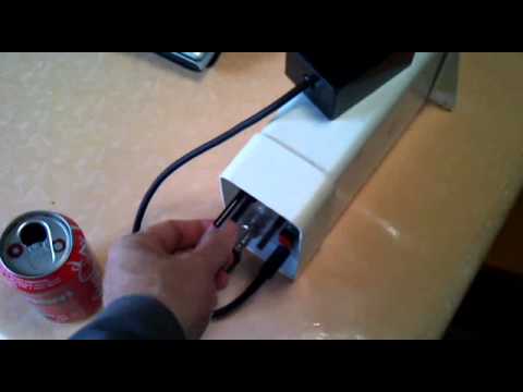
My original unmodified Delta Pulse of Elbombaci, 45x45cms coil. Detects coke tin of 110cm.
Excused my bad EnglishComment
-
61 6C 20 64 72 61 6B 75 20 6A 65 73 74 20 74 75 20 62 72 20 64 72 61 6B 75 6C 65 20 21 21 20 68 68 65 65 hhee!!Comment
-
Originally posted by draco View Post
Hi nice work. But see if detect Gold and what the the size and deep?
Make tested not with aluminum and silver and answer me please
Good luck
NicolasComment
-
Hi OrbitOriginally posted by Orbit View Post
I'm not sure if that was a cry for help or not, but your hex code for the start of the Delta Pulse LCD code for PIC 18F252 is incorrect!
The first two lines of the start code for the demo hex (provided in the discriminator.rar file) by Japanese and Freedan3d were the following:
:0600000000F00BEF00F020
:10000800FFFFFACF23F1FBCF24F168EF0BF0FFFFDE etc. etc.
whereas the first two lines of the start code for the full hex are the following:
:020000040000FA
:1000000000F00BEF00F0FFFFFFFFFACF23F1FBCF73 etc. etc.
so I'm not sure where you obtained the partial hex code from, that you posted on this forum...
To Saromines Ramiel:
Hi Saromines Ramiel
I'm glad you solved your problem with the LCD (running character on top of LCD). Well done!
I would like to reiterate what I have suggested before that out of respect for our master technician and teacher, Elbombaci (aka Uykusuz, Sleepless, Ahmet Akgöz), who has contributed enormously to these wonderful
metal detector projects and without whom these projects would not be possible for the amateur (like me), we cannot upload the full hex file without his permission.
Alternatively, because I would like to build my third metal detector, namely, the PIM-2, if anyone has the full hex file for the PIM-2 v.05 or .06 (not demo), I will arrange a fair exchange for my file.
Please PM me.
Obrigado
Ciao
Speedy_GComment
-
Hello Nicolas, a ring as I show in the photo it detects about 35 cms. No I have a gold nugget, so I can not give you other information. The coil is too large to detect small things, besides this detector is configured to be very sensitive to small nuggets.Hi nice work. But see if detect Gold and what the the size and deep?
Make tested not with aluminum and silver and answer me please
Good luck
Nicolas
Greetings
Comment
-
Thanks Speedy_G, i don,t have a full hex of PIM-2,.also a demo but if possible to send me full hex of DP2 this my [email protected] thanks again speedy_g..
best time!
Saromines RamielComment
Comment