Announcement

Collapse
No announcement yet.

Bulgarian 'PULSE STAR' (... close to Legendary one)

Collapse
X
 
  • Filter
  • Time
  • Show
Clear All
new posts

  • ok
    thank you very much. i use 7909 instead 79l09.7808 instead78l08.7606 instead 76l06.lm -5v(picture above ?)instead lm -12volt.
    for example 78l08 is and 7808 is.
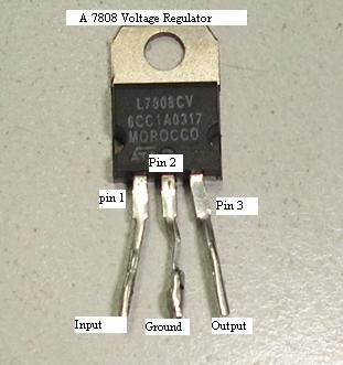
    what the mistake.that is too funny.if you dont say me i dont know what is my wrong.
    i now go and buy them.tomorrow say to you .
    regards and thans

    Comment


    • Hello to my dear georgi
      I buy them and change on my board (just 78L08 instead 7808,79L06 to 7606,Lm2940 5v to Lm2940 12v)and again check pcb and all components and all is true but when i connect the adaptor 15v and 1000mA , all off my out put is nearly +15v or -15v.and not part going to hot and i check again but not understand .becuase i upload my picture and pcb file for your help me.please.

      http://ir2up.ir/up19/02613621473001.zip
      reagards

      Comment


      • Originally posted by mohandes View Post
        Hello to my dear georgi
        I buy them and change on my board (just 78L08 instead 7808,79L06 to 7606,Lm2940 5v to Lm2940 12v)and again check pcb and all components and all is true but when i connect the adaptor 15v and 1000mA , all off my out put is nearly +15v or -15v.and not part going to hot and i check again but not understand .becuase i upload my picture and pcb file for your help me.please.

        http://ir2up.ir/up19/02613621473001.zip
        reagards
        Why not solders ?http://i072.radikal.ru/1303/d8/5e5ab8fb8822.jpg

        Comment


        • Hello georgi
          that was my old board .
          my new board are :


          http://ir2up.ir/up19/f2613621643371.jpg
          http://ir2up.ir/up19/f2613621643372.jpg
          http://ir2up.ir/up19/f2613621643373.jpg
          http://ir2up.ir/up19/f2613621643374.jpg

          now again check please
          regards

          Comment


          • i explain for you in this picture


            http://ir2up.ir/up19/c2013621653081.jpg
            thanks

            Comment


            • Now i ask another obscurity.between which pins can i measure?for example for +8v i must be put the prop com multimeter on negetive battery and another prop put the pin1 v8L08.correct.
              sorry me for my ordinary questions.
              thanks

              Comment


              • today I check again but my opinion the pcb and set parts have not error.
                but when i connect the adaptor 12.5v all of my out put are 2 or 4 volts or near that.and just +8volts give it to me 24.5 volts.
                I make four pcb of schematic Alexis (pertaining georgi)and when I can not answer my supply board another board are Useless.I real need help
                regards

                Comment


                • Originally posted by mohandes View Post
                  today I check again but my opinion the pcb and set parts have not error.
                  but when i connect the adaptor 12.5v all of my out put are 2 or 4 volts or near that.and just +8volts give it to me 24.5 volts.
                  I make four pcb of schematic Alexis (pertaining georgi)and when I can not answer my supply board another board are Useless.I real need help
                  regards
                  Power is the simplest part of the P. Star, you have many problems. Another part of the scheme is more complex, you will have many problems.Scheme is very complicated for you,sorry .STOP!

                  Comment


                  • ok.I FOUND MY BIG PROBLEM AND THAT WAS ADAPTOR.
                    I give this voltges 8.11v,-7.36v, -11.25v , -10.25v ,-12.02v . my battery are 8*1.5v=12v.
                    in your schematic the voltages are +8,-7 ,-10.6(i give -11.25),-10(i give -11.15v),-12v.are my values good?
                    and my led always is on.why?
                    one prob located on the Gnd of curcuit(com prob)and another on the out put?correct i think
                    regards & thanks

                    Comment


                    • Hello georgi
                      If my answers is good i connect output to another boards.why led in supply board is always on?????????
                      thanks

                      Comment


                      • Hello georgi.
                        I finish the psg .i check the all my pcbs and all is correct.when i connect all pcb together1- my speaker not sound tic-tic(is 32ohm)
                        and2- my voltages +8,-10.6(i give -11.25),-10(i give -11.15v),-12v are down.
                        3-my battery is near 14v,when i connect it my led in supply board always on Until my battery have 12.3v and next it is off.
                        because i havent oscilloscope i can not test it and should go to collage.
                        please help me my voltages corect?i measurement true(one prob located on the Gnd of curcuit(com prob)and another on the out put)
                        thanks

                        Comment


                        • I find my problem dear georgi.
                          it is in my first board(hve 2 4538, and 1 4053,..) and the error in Ic Ne5532.when i set this 8 volts down and near 2 volt.what?
                          thanks
                          first is 5532 and second is NE5532.
                          can i use ne 5534 ?


                          pleas help

                          Comment


                          • i take photo and paste for you

                            http://upload.tehran98.com/img1/uiqj0kcgrzukhi3der.jpg
                            regards thanks

                            Comment


                            • I just want know is the Voltage drop natural?
                              or say me tha values of x y z
                              no body help

                              Comment


                              • ok
                                georgi hi
                                i buy lf357n and replaced to ne5532(alexis schematic) but have a few problem
                                1-in pin 3 ne555 have -10.35v and in pin 6 lf357n have 5.6v and in drain(irf740)have not 600 volt.what is the mistake?please help
                                and my pcb have not problem.and chek all parts and all are true.
                                thanks

                                Comment

                                Working...
                                X