Announcement

Collapse
No announcement yet.

Digital volume for square waves in Arduino Nano.

Collapse
X
 
  • Filter
  • Time
  • Show
Clear All
new posts

  • Digital volume for square waves in Arduino Nano.

    This library is good for any Atmega328P board to generate square waves at controllable volumes. It replaces a mechanical sound pot by programattically setting the volume via a menu and up/down buttons, rotary encoder etc. It can even modulate the sound with attack, sustain and decay to (see examples inlcuded in the library).

    This is how it works:

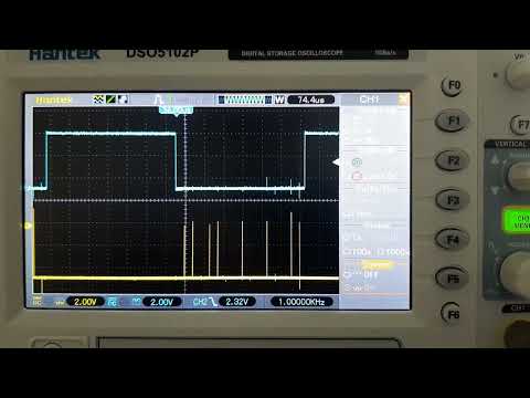
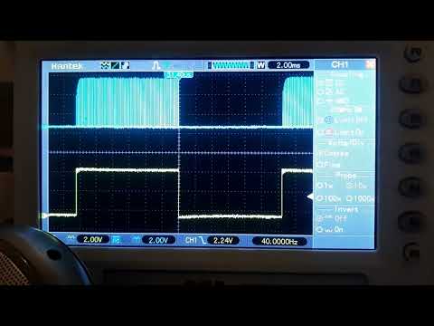
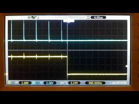
    - Timer0 produces a PWM signal at a fixed frequency beyond the audible spectrum (62.5 KHz).
    - Timer2 produces a square wave whose frequency can be set by the application.
    - TImer2 gates the output of TImer0 (pass if high, clear if low).
    - The volume of the square wave of TImer2 will depend on the duty cycle of Timer0 (set by the application).

    The sound is output to the OC0B pin (D5). Add a simple RC filter and you're set.

    Click image for larger version  Name:	20240203_175731.jpg Views:	0 Size:	450.2 KB ID:	419742

    ​​​​​​


    Example code to generate a frequency with a given volume:

    Code:
    #include "VolumeSquareWaveNano.h"
    
    VolumeSquareWaveNano v;
    
    void setup() {
      // put your setup code here, to run once:
      v.init();
    }
    
    void loop() {
      // Just a frequency at 50% volume
      v.setFrequency(2000);
      v.setVolumePercent(50);
      while(1);
    }​
    To install the library, go to your sketches folder and create a "library" subfolder (if not yet there). Extract the "VolumeSquareWaveNano" folder to said subfolder. Inside there's an "examples" subfolder with three simple demo sketches.

    VolumeSquareWaveNano.zip
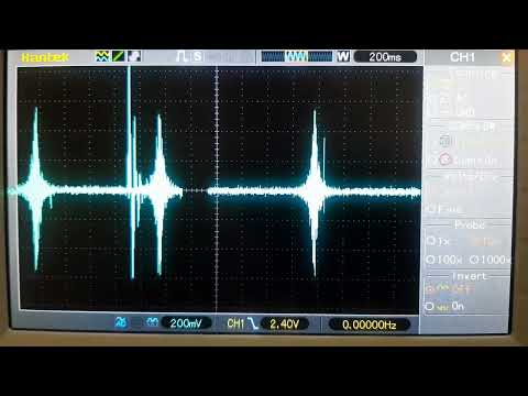
    Heartbeat:


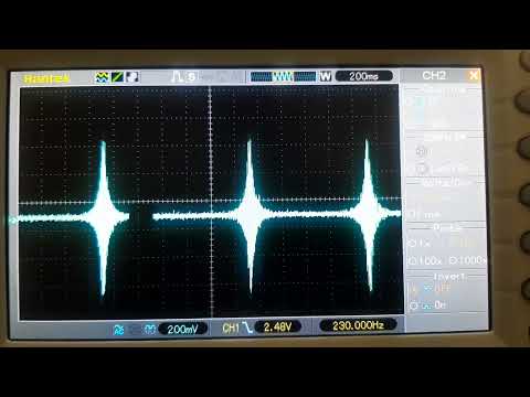
    Simple bell-like modulation of two tones:


  • #2
    This is an improved version of the library.

    VolumeSymetric.zip

    The PWM modulation is now symmetric. For example, if the duty cycle during the "on" time of the square wave (yellow trace) is 75% then the duty cycle during the "off" time is 25%. The resulting low-pass sound wave (blue trace) is centrered around Vcc/2 and is perfectly symmetric.

    Click image for larger version  Name:	20240204_154640.jpg Views:	0 Size:	714.7 KB ID:	419807

    The modulation signal (unfiltered Timer0 output, blue) looks like this

    Click image for larger version  Name:	20240204_153659.jpg Views:	0 Size:	915.4 KB ID:	419808

    The sound produced is free from cracking artifacts because the DC bias is fixed to Vcc/2, unlike the former library.

    This is an example of the sound caused when sweeping in and out of a target by modulating both the frequency and amplitude as a function of the target signal. Base frequency is 216 Hz. See the sketch "target.ino" in the examples folder.


    And this is how it would sound with amplitude only modulation.

    Comment


    • #3
      fatal error: VolumeSquareWaveNano.h: No such file or directory

      Comment


      • #4
        Originally posted by pito View Post
        fatal error: VolumeSquareWaveNano.h: No such file or directory
        How did you do the installation?

        The unzipped files should look as follows:

        PHP Code:
        (Your sketches folder) - "Documents\Arduino" in my case
         |
         |
        _VolumeSymmetric
            
        |
            |
        _ _VolumeSymmetric.cpp
            
        |_ _VolumeSymmetric.h
            
        |_ _examples
                  
        |_ _demo1
                  
        |     |_ __demo1.ino
                  
        |_ _demo2
                  
        |       |__demo2.ino
                  
        |_ _halloween
                  
        |       |__halloween.ino
                  
        |_ _nutcracker
                  
        |       |__ nutcracker.ino​
                  
        |_ _target
                  
        |       |__target.ino
                  
        |_ _twinkle
                          
        |__twinkle.ino​​​​ 
        Latest version

        https://www.geotech1.com/forums/file...etch?id=419973
        Attached Files

        Comment


        • #5
          I didn't, I do not see a zip file for it .

          Comment


          • #6
            Originally posted by pito View Post
            I didn't, I do not see a zip file for it .
            Try this link

            https://www.geotech1.com/forums/file...etch?id=419973

            Pin D5 is the Timer0 output (speaker)
            Pin D3 is the raw frequency of TImer2 for testing (trigering the scope, for example)

            Comment


            • #7
              zip library - know how to add a zip library to arduino but not separate cpp. and h. files which are in your folder.

              Click image for larger version

Name:	image.png
Views:	104
Size:	68.6 KB
ID:	419979
              Attached Files

              Comment


              • #8
                Originally posted by pito View Post
                zip library - know how to add a zip library to arduino but not separate cpp. and h. files which are in your folder.
                I don't understand what the problem is.

                Just unzip and then in Arduino IDE open one of the examples, "demo1.ino" is the simplest, and look how they're coded.

                PHP Code:
                #include "VolumeSymmetric.h"

                VolumeSymmetric v;

                void setup() {
                  
                // put your setup code here, to run once:
                  
                v.init();
                }

                void loop() {
                  
                // Just a frequency at 50% volume
                  
                v.setFrequency(2000);
                  
                v.setVolumePercent(90);
                  while(
                1);
                }
                ​ 

                Comment


                • #9
                  The problem is that the .h and .cpp files both need to be in the same directory as the sketch.
                  Simply copy the two files into the demo1 folder (for example) and the sketch will compile.

                  Comment


                  • #10
                    Click image for larger version

Name:	image.png
Views:	118
Size:	188.7 KB
ID:	419982
                    Just unzip and then in Arduino IDE open one of the examples, "demo1.ino" = I did

                    Comment


                    • #11
                      Originally posted by Qiaozhi View Post
                      The problem is that the .h and .cpp files both need to be in the same directory as the sketch.
                      Simply copy the two files into the demo1 folder (for example) and the sketch will compile.
                      Strange, in my Arduino IDE (2.2.1) that requirement is not necessary.

                      I think I should have put those files under a "src" folder.

                      Try this: in the VolumeSymmetric folder create an "src" subfolder and move the .ccp and .h there.

                      This zip has the correct directory tree

                      VolumeSymmetric.zip

                      https://www.geotech1.com/forums/filedata/fetch?id=419984&d=1707346796
                      Attached Files

                      Comment


                      • #12
                        need to be in the same directory as the sketch. = ok, done
                        Click image for larger version  Name:	image.png Views:	0 Size:	27.6 KB ID:	419986
                        This sketch is using i ++, how to change to arduino analog pin ?

                        Comment


                        • #13
                          Originally posted by pito View Post
                          need to be in the same directory as the sketch. = ok, done
                          Click image for larger version Name:	image.png Views:	0 Size:	27.6 KB ID:	419986
                          This sketch is using i ++, how to change to arduino analog pin ?
                          You can't change the pin. It's fixed and it's D5.

                          Comment


                          • #14
                            D5 = output, input pin ?

                            Comment


                            • #15
                              Originally posted by pito View Post
                              D5 = output, input pin ?
                              D5 is PWM output for the speaker. You don't need to configure it, it's already done in the code and can'r be changed.

                              Comment

                              Working...
                              X