
 Tweet
Tweet
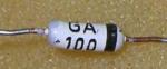
What could you use for the GA100 diode ????
-
-
This looks like a simple regen cctComment
-
-
These ccts appear to be a simple regenerative circuit
to find out how they work search for "Regenerative receivers"
The value of R3 470K in the positive rail of the 2nd cct is way too high
I believe it should be 470 ohms as shown in the 3rd cct
and your typical 2n2222 tranny should work in this cct
you should be able to test your cct to see if its oscillating
by placing the cct close to a am radio tuned off station
and listen for the hash
simple but brilliant
Basicly what I think is happening is transistor one is biased to the point of oscillating
at a frequency determined by the tuned cct (L1/C1) approx 100KHZ
this induces a voltage into the second coil (L2) which
switches transistor two on and from there the LED
and as you bring metal close to the coil it
dampens the oscillations, (and maybe even stops oscillating)
and as you wave the metal back and forth over the the coil L1
the voltage in L2 varies and
this switches T2 on and off and the led (and motor, buzzer etc)
something like that , I think you will get the idea
Coils are built on a ferrite rod from the antenna of a broadcast AM radio. L1 has 120 turns and L2 is 45 turns 0.3mm diameter magnet wire.Comment
-
I have started this project
and wound the coil on ferrite rod
I might try the dead bug method
Comment
-
Just found this other thread , linking it here as has some good info in it, and some better ccts
http://www.geotech1.com/forums/showt...ght=pinpointerComment
-
Can someone please guide me, what is IC in this circuit, and is there a russian/english document for semiconductors and chips. Also what is part connected between pins 2 and 3Comment
-
You can use this site: http://radio-hobby.org/modules/analog/
К561ЛА7 = CD4011
КД522 = 1N4148
КС147 = BZY83C4V7
АЛ307 = GREEN LED
КТ3102Б = BC546
КТ315 = 2N3397, 2SC388
КП307 = 2N5394
КТ361Г = 2N3905Comment
-
ThanksComment
-
Also what is part connected between pins 2 and 3
http://www.electronicecircuits.com/w...figuration.jpgComment
-
ussr refComment
-
Many thanks, now i try to make. Why is used relay here? To switch off VD4 LED?Comment
-
from text. there is additional possibility to work on a distance..... for example from water surface... so
to those points attached a connector for a cable.Comment
-
Thanks for explanation.Comment
Comment