Announcement

Collapse
No announcement yet.

Popular Electronics, Feb. 1969

Collapse
X
 
  • Filter
  • Time
  • Show
Clear All
new posts

  • #31
    Good job Esteban! I was about to go digging for it tomorrow, the curiosity was starting to get to me!

    The question I have - could this be the world's first VLF detector??

    Comment


    • #32
      Originally posted by Qiaozhi View Post
      Hi Esteban,

      Please email it to me at [email protected] and I will upload it here.
      Hi Qiaozhi.

      Sent you the article.

      Regards

      Esteban

      Comment


      • #33
        Originally posted by technos View Post
        Good job Esteban! I was about to go digging for it tomorrow, the curiosity was starting to get to me!

        The question I have - could this be the world's first VLF detector??
        Thanks. Is some strange detector...

        Comment


        • #34
          Originally posted by Esteban View Post
          Hi Qiaozhi.

          Sent you the article.

          Regards

          Esteban
          The PDF size limit is actually 2MB, and this file is 1.6MB.
          It appears that you could have posted this ok without any errors.
          Anyway, no problem. Here it is ->
          Attached Files

          Comment


          • #35
            Originally posted by Qiaozhi View Post
            The PDF size limit is actually 2MB, and this file is 1.6MB.
            It appears that you could have posted this ok without any errors.
            Anyway, no problem. Here it is ->
            Ahhh! In the past was 1 M, this size is my mind, so no try attached it!

            Comment


            • #36
              Final Block diagram

              Thank you all. Explored is the block diagram of the two projects by Leslie Hoggard and their handicaps. This is the block diagram of which should work most economical IBR metal detector (Induction Balanced Regenerator).
              Attached Files

              Comment


              • #37
                Originally posted by mikebg View Post

                Thank you all. Explored is the block diagram of the two projects by Leslie Hoggard and their handicaps. This is the block diagram of which should work most economical IBR metal detector (Induction Balanced Regenerator).
                Excellent mikebg. Thank you.

                Is it possible to convert block diagram into working schematic?

                Display processor can be eliminated to get economical and simple IBR.

                What is purpose of fase shifter inside feedback line to Tx stage?

                Comment


                • #38
                  WM&,
                  The Barkhausen's criterium is written simple in block diagram as Z x Y>1, but Z and Y are complex functions with Re and Im parts (or magnitude and phase) depending on frequency. Written with magnitude and phase, the Barkhausen's condition for oscillations means:
                  1. There is one or more frequencies at which
                  A1 x A2 x A3 x A4 x A5 x A6 > 1,
                  where Ai is amplification (gain) of i-th block. We need GAIN control in block 6 to adjust threshold of oscillation.
                  2. There is one or more frequencies at which
                  ф1 + ф2 + ф3 + ф4 + ф5 + ф6 = 360 deg,
                  where фi is phase lag of i-th block. To discriminate targets, we need PHASE control in block 5 to select frequency of oscillation in region where targets differs in transfer impedance Z2=Re+jIm. The phase of target signal is
                  ф2=artan(Im/Re).
                  We need DISPLAY PROCESSOR to transform frequency of TX oscillation in a comfortable audio frequency and/or to demodulate it producing DC signal for visual indicator.
                  Since in the 1969 project "Different" is missing a block 7, the operator must hear the frequency of oscillation. This is very annoying for discrimination and as sound if it is above 2KHz.
                  Leslie Huggard published "Houndog" metal detector 10 years after the publication of "Different" metal locator . The principle of operation is the same: sensing network connected in regenerative loop. The author had 10 years to improve the block diagram and introduce missing in project "Different" blocks AUDIO DISPLAY and PHASE SHIFTER. This is indeed done. For audio display using Amplitude demodulator with Q1 and piezoelectric buzzer. For phase shift and balance using potentiometer R7 and capacitor C7. However, these components change phase in steps. Potentiometer R7 regulates fine balance of input voltage induced by mutual inductance between TX coil L3 and RX coil (L1+L2), but in balancing point, the phase reverses in 180 deg.
                  Phase should be adjusted gradually in region where targets vary in phase.
                  Attached Files

                  Comment


                  • #39
                    The DISPLAY PROCESSOR

                    In this circuit diagram, IC1b, IC1c, IC2 and X1 are used for block 7 - DISPLAY PROCESSOR. They operates as BFO for audio discrimination.
                    Attached Files

                    Comment


                    • #40
                      Originally posted by mikebg View Post
                      WM&,
                      The Barkhausen's criterium is written simple in block diagram as Z x Y>1, but Z and Y are complex functions with Re and Im parts (or magnitude and phase) depending on frequency. Written with magnitude and phase, the Barkhausen's condition for oscillations means:
                      ts vary in phase.
                      I too have been looking at simple detectors. The only question I have is whether this circuit oscillates until in the presence of metal? That is, in order for the feedback circuit to oscillate it needs to have a change of inductance in the bridge circuit. Which is quite different from detecting an already transmitting signal as a VLF/TR does, and more like a BFO actually. In turn this would be limiting to depth by quite a bit.

                      Comment


                      • #41
                        Originally posted by technos View Post

                        In turn this would be limiting to depth by quite a bit.
                        Which solution by your mean "would be limiting to depth": oscillating or non-oscillating in "0" position?

                        Comment


                        • #42
                          Originally posted by WM6 View Post
                          Which solution by your mean "would be limiting to depth": oscillating or non-oscillating in "0" position?
                          Inductors L1/L2 along with potentiometers R6/R7 form a bridge circuit that are adjusted to be in balance. The bridge circuit feeds the LM386 acting as a differential amplifier. Since the bridge is in balance, there is no voltage on the output of U1 LM386. When a metal target (a coin) enters within range of coils L1/L2 their inductance will change, producing a voltage on the output of U1. This feedbacks through coil L3 C6/C7 and causes U1 to oscillate at that tank frequency. Simultaneously this current turns on Q1 and the buzzer.

                          Until there is a metal object within range of L1/L2, there is no oscillation and hence there is no transmitted signal like a VLF/TR. Such a signal has photons that can go a certain distance, whose strength follows the inverse square law. http://hyperphysics.phy-astr.gsu.edu...orces/isq.html

                          Inductive coupling, on the other hand, does not follow the inverse square law, but rather falls off much more rapidly. So greatly generalizing;

                          Field Intensity at distance d away from coil I [vlf/tr] 1/(d^2) > 1/(d^d) [intensity of flux aka change of inductance]

                          This is not exact formulas, and is an apples and oranges comparison. But think of a magnet only attracting something a few inches away as compared to a beam of flashlight that can go yards away.

                          BFOs because they rely upon the change of inductance (and hence creates a difference of frequency that "beats") in their coils fall under this as well.

                          Under this light, this "hounddog" circuit is kind of a "dysfunctional" circuit in this respect, as the circuit is "held up" by L1/L2 bridge circuit rather than detecting the oscillating signal thrown off by L3 (and then the target).

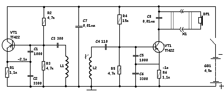
                          To have a true TR circuit you would need to rearrange the circuit to something like the link (presumably Russian) Qaiozhi posted above, where an oscillator is continuously operating. Printed in 1972 way before it's time, and only four transistors. Does anybody know where it first appeared?
                          Attached Files

                          Comment


                          • #43
                            Originally posted by mikebg View Post
                            In this circuit diagram, IC1b, IC1c, IC2 and X1 are used for block 7 - DISPLAY PROCESSOR. They operates as BFO for audio discrimination.
                            Hi mikebg,

                            Please tell us more about BFO schematic that you post and it's performance,

                            did we can build one good deep BFO metaldetector ?

                            thanks...

                            Comment


                            • #44
                              Originally posted by technos View Post

                              To have a true TR circuit you would need to rearrange the circuit to something like the link (presumably Russian) Qaiozhi posted above, where an oscillator is continuously operating. Printed in 1972 way before it's time, and only four transistors. Does anybody know where it first appeared?
                              Thank you technos for your kind explanations.

                              Yes, circuit is from russian source. Unfortunately, it is easy only regarding the number of semiconductors, but also requires the winding of trafo, which is very annoying work.

                              I am interesting in such simple (Tx oscillating) version of T/R schematic, only not trafos inclusive, to do some test.

                              Comment


                              • #45
                                Originally posted by technos View Post

                                To have a true TR circuit you would need to rearrange the circuit to something like the link (presumably Russian) Qaiozhi posted above, where an oscillator is continuously operating. Printed in 1972 way before it's time, and only four transistors. Does anybody know where it first appeared?
                                Comments on Fig.3 are Bulgarian.

                                Another interesting construction:


                                http://cxem.net/metal/Part6/6-8.php

                                or this:

                                Comment

                                Working...
                                X