Announcement

Collapse
No announcement yet.

LOOKING FOR GOLDSCAN 4 Schematic.

Collapse
X
 
  • Filter
  • Time
  • Show
Clear All
new posts

  • I think it should, measure the current consumption, which should be 200 to 250 mA.
    The voltage should not be too high 15 or 16 volts, with those values ​​and a good heat sink in the regulator, should not have problems. The scheme indicates 3.5 ohms for the coil, see the first page, scheme published by KT315 https://www.geotech1.com/forums/atta...6&d=1123969824

    Comment


    • Originally posted by Jose View Post
      For the case of Q9 and Q10, the "S" terminal is connected to ground or GND. The attached diagram is correct, although there could be some error.[ATTACH]44349[/ATTACH]


      Greetings and regards jose.
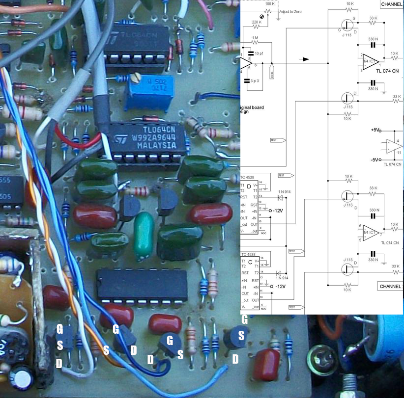
      I suspect your goldscan 4 in this photo.
      between the scheme here and your goldscan pcb array j113 s different connection.
      Drain pins on the diagram are connected to the integrated. but drain on the pcb is shelf. is the correct connection?

      Comment


      • Originally posted by TufaN View Post


        Greetings and regards jose.
        I suspect your goldscan 4 in this photo.
        between the scheme here and your goldscan pcb array j113 s different connection.
        Drain pins on the diagram are connected to the integrated. but drain on the pcb is shelf. is the correct connection?


        Your attachment seems to be missing, but Source & Drain are interchangeable on J113

        Comment


        • [QUOTE = 6666; 260390] Your attachment seems to be missing, but Source & Drain are interchangeable on J113 [/ QUOTE]

          Comment


          • The data sheet says
            "J111 / J112 / J113 / MMBFJ111 / MMBFJ112 / MMBFJ113N-Channel SwitchFeatures• This device is designed for low level analog switching, sample and hold circuits and chopper stabilized amplifiers.• Sourced from process 51Source & Drain are interchangeable"

            Comment


            • some data sheets say nothing
              Attached Files

              Comment


              • Because I don't speak English. I guess what I mean is not understood.

                Is it right to my damask. or pcb that has been lined up correctly. which layout works

                Comment


                • It is the image of my GS4.
                  The fet used, is the BF245A. The terminals are connected as shown in the image below.Click image for larger version

Name:	GS4 BF245A.jpg
Views:	1
Size:	216.5 KB
ID:	354844

                  Comment


                  • Originally posted by Jose View Post
                    It is the image of my GS4.
                    The fet used, is the BF245A. The terminals are connected as shown in the image below.[ATTACH]47346[/ATTACH]


                    Jose I get it now. Thanks very much for the return.

                    Comment


                    • hello jose. I'd like to know one more thing. Alex has drawn both schemes. which one is right?
                      Attached Files

                      Comment


                      • Alex's original scheme does not include the GND connection of the fet.
                        Two 470K resistors were added on both channels.
                        A 220K resistor was replaced by 22K.
                        Use the scheme indicated below, it is the one that works on my GS4.Click image for larger version

Name:	GS4 Correct.PNG
Views:	1
Size:	215.6 KB
ID:	354860

                        Comment


                        • see the first page, scheme published by KT315

                          ---
                          Jose
                          i have 2 files in DipTrace and see in its header an authour 'Jose'. this are you done?

                          Comment


                          • Originally posted by kt315 View Post
                            see the first page, scheme published by KT315

                            ---
                            Jose
                            i have 2 files in DipTrace and see in its header an authour 'Jose'. this are you done?
                            The two schemes that I published in diptrace, correspond to Goldscan 5, The first part and the audio, are very similar to the Proto scheme published by Altra.
                            I have a functional prototype, but the schemes and the pcb are not complete or updated.

                            Comment


                            • thanks jose. a short video of my first tests

                              Comment


                              • Hello friends, I want to make the Golden Scan metal detector two-tone. I want you to make the right scheme

                                Comment

                                Working...
                                X