Announcement

Collapse
No announcement yet.

silver saber circuit

Collapse
X
 
  • Filter
  • Time
  • Show
Clear All
new posts

  • silver saber circuit


    Hi All:

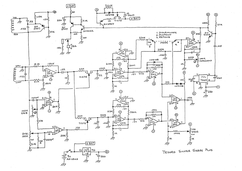
    Here's a circuit fo the Silver Saber plus. It looks like there's an error in it... there's no provision for creating the negative voltage. I'm guessing there's a second regulator connected to the battery to create a -5v current that was ommitted.

    I wish there were some details about the search coil, but you can't have everything. I may try to build this one, and hope that I can adjust it... I have doubts about my abilities. Looks like a very nice detector, though.

    Have fun
    BG

  • #2
    Re: silver saber circuit

    BG,

    The 7660 chip (far right side) generates the negative supply. It's a voltage inverter chip, uses switches and caps (the 220uF ones) to make a switched power supply.

    The coil inductance numbers for std Tesoro coils are 5.75mH on the TX and 6.2mH on the RX. Of course, you'll have to figure out how to split off the TX bucking coil.

    - Carl

    Comment


    • #3
      A dumb question, but I GOTTA ask...

      Carl:

      Thanks for your reply, but I've got to ask... what's a bucking coil? I'm afraid you're dealing with a MD design neophyte here... is it something that's specific to tesoro searcheads, or is there something in the circuit that I'm missing?

      I wouldn't bother you, but I really am considering trying this one out. And, heck, since I'm bothering you anyway, I may as well ask a couple more. I read somewhere that IC sockets are a bad idea due to stray capacitance... true or false with this circuit?

      And in the same vein, (stray capacitance, that is) I was considering using a "modified ugly bug" type of construction, where I break the design into smaller blocks, and solder up the circuit directly on the leads in places where it makes sense... you know, feedback resistors and caps, that sort of thing. Is this a dumb idea?

      Thanks for your help
      BG

      Comment


      • #4
        comments

        A "bucking coil" is what some other people call a "feedback coil"-- in the case of a concentric coil assembly, a third coil wound in series (usually with the transmitter) but in opposite phase, for the purpose of producing induction balance. DD searchcoils usually don't use feedback coils.

        IC sockets shouldn't cause problems in this circuit. However, IC's these days are extremely reliable, and the only reason I know of to socket IC's, is if you're inexperienced with electronic construction and are afraid you may wire something wrong and turn silicon into smoke, and want an easy way to recover from your mistake.

        Ugly bug construction is fine for a simple RF circuit, but this is a bit complicated for that, and isn't fast enough to require the ground plane advantage afforded by good ugly bug construction. For this circuit, I recommend ordinary unclad perfboard, with components installed as compactly as possible.

        --Dave J.

        Comment


        • #5
          Re: comments

          DON'T forget the "guard rings" around the JFET op-amp inputs (pins 2 & 3).. Tesoro did!!

          Comment


          • #6
            Re: comments

            Thanks for the reply, Dave.

            One thing about IB coils: even if you know what inductances you want, including the amount for the bucking coil, they're still hard as hell to make. It is FAR FAR better to use std manufactured coils, and there are heaping gobs to choose from. Adapting for different manufacturers is not hard.

            IC sockets are also useful if you want to try out different opamps.

            - Carl

            Comment


            • #7
              Re: DDumb question ?

              I am guessing that a DD coil would suit the circuit and be easier to make if that route were chosen ?
              If that is the case , if a 2nd hand coil at the right price turned up it wouldn't matter if it was dd or concentric.
              Am i right in thinking that coils can be "tuned" to the detector by altering their capacitance?
              I will experiment when time allows on breadboard or perf. board , whichever comes to hand soonest.
              Finally , this may also be a dumb question but what are "Guard rings" please ?

              Comment


              • #8
                Re: comments

                One thing I've learned about electronics over the years. All components have smoke in them. If you wire something up wrong and let the smoke out, they don't usually work anymore :-)
                Charles

                Comment


                • #9
                  Re: DDumb question ?

                  Hi Peter,

                  I will take a stab at a couple of your questions. First, the guard rings, normally if an FET input opamp is used in a "high impedence input environment, such as a sample and hold, manufacturers will place a small pcb copper trace partially surrounding the input pin of the opamp. This is to reduce leakage currents, or maybe, induced currents which could upset the ciruitry.

                  If you have such a pcb you can look at, that has FET input opamps, just look to see if there isn't a small trace that partially surrounds the input pin or pins of the opamp.

                  Now, to the different types of coils. Some manufacturers place the caps in epoxy which can make it difficult to make substitutions or changes. It is impossible to tell you which ones do this and which ones do not. It gets more difficult, since some manufactures have changed their coil designs over the years, due to manufacturing processes, so, some of their coils may be relatively easy to modfiy, and others are not.

                  Sometimes, it is easier to design a circuit that matches a particular coil, rather than the other way around.

                  As to DD and coplaner coils, it has been my experience that coplaner coils are more forgiving. It is also my opinion that they are used more often because they are easier to make than a DD. My experience, which is very limited when it comes to experimenting with modifying coils, has been that a DD can be very tough to work with. They are tough to "tune" and tough to keep in tune. That is why some manufacturers epoxy eveything in place.

                  Several years back, I visited one of the manufactures and saw some of the little techniques used, like the special coated wire that, when moistened with alcohol would adhere to adjoining windings.

                  When the coils were finally position, all was epoxied and then subjected to heat during curing so the epoxy would harden in a heated environment. This reduced the possibly of the epoxy softening if the coil were to be subjected to high temperature conditions, which can happen if a detector is left in the trunk of a vehicle in a location where the temperature exceeded 100 degres or more.

                  I have looked in several coils but have only modified a few, and most weren't as successful as I had hoped. So, I am sure, people like Carl has had more experience and better info as to which coils may be the best to work with.

                  Reg

                  Comment


                  • #10
                    Re: DDumb question ?

                    Not much experience here with coils. Like you, I've taken some apart, but I have not tried to modify any. My comment in another post about using various manufactured coils was in reference to building a homebrew. I would design around a certain coil type as that's easier than building coils.

                    I have messed some with putting coils on different machines. I think in many cases detectors can be made to accept other coils with some minor mods, mostly in tuning caps. I successfully put a Lobo DD coil on a CZ-7, and am now modifying a Bandido to take the Lobo coils. But for the most part, doing this is a lot of trouble and not worth it unless the coil you want to use is somewhat unique.

                    I also saw a manufacturer's setup for winding coils using adhesive magnet wire. Pretty slick! I think all manufacturers now use this kind of wire. Don't know where to get it tho.

                    - Carl

                    Comment


                    • #11
                      Re: Special wire

                      Hi Carl,

                      I bought some several years ago and experimented with it. It is pretty neat.

                      Wiretron has it listed as a special coating that is alcohol or heat activated. They have a special name for the outer coating, but don't remember it. It is listed on their insulation guide.

                      Reg

                      Comment


                      • #12
                        Re: Silver Sabre circuit ***IMPROVEMENTS***

                        You could try different Op-Amps in the SS circuit, but if you look LONG and HARD at the existing ones, you wont find any which are better them in the areas which matter most.

                        You COULD try ones like the National Semiconductor LF353N (MUST be the N, as it's an "improved" version of the standard LF353.

                        I believe there's a newer version of the '442 as well which has better a current noise figure.

                        The "bottom" signal path has a constant retune and Isuspect is the "motion" path. Changing the time constants of the two "auto balancing" circuits i.e. the LF442 and the LM358 blocks, simply involves changing BOTH the 330K resistors.

                        You could try starting at 470K. This will "theoretically" give you better sensitivity to small items. Too high a value, and you will "smear" the motion signal.

                        Also, changing the value of the two 150K resistors on the "front end" LF353 to 330K will give a marginal improvement in depth and sensitivity, but too much will make the GB setting a LOT more critical, as well as making the detector VERY unstable.

                        Replacing the TIS75 VERY CRUDE synchronous demodulators with REAL "full time" demodulator circuits which also sample the negative portion of the target signal, will SIGNIFICANTLY reduce the system noise levels and drift, and make a much more stable machine.

                        Other methods are to amplify the incoming signal, and phase shift the ground and discriminate signals DIRECTLY, this means that you could dispense with the "wandering" Colpitts type TX oscillator in the top lefthand corner, and drive the thing with a crystal (VERY STABLE) one. Using a buffered take off of the coild drive signal for the Demodulator switching signal also reduces noise as it eliminates clock "jitter".

                        Finally, use "metal oxide" resistors THROUGHOUT, they're a LOT quieter than the cheap carbon ones used by Tesoro, and use OFC cable to do ALL the link-up. Keep ALL cables as SHORT as possible, and use screened cable if you can, only connect ONE END of the screen when running a single wire to controls, this will avoid creating multiple paths for any noise picked up on the screening, also connecting the screens at ONE COMMON point in a "star" ground will also help.

                        I could list over 30 simple and immediate improvements which took me just over two hours to come up with, but Tesoro aren't going to pay me for them.

                        Hope someone finds this info useful.

                        Comment


                        • #13
                          Re: Silver Sabre circuit ***IMPROVEMENTS***

                          I've printed your posting , Sean , and as I'm no engineer it has given me some good starting points for experimentation , (I'd already cottoned on to the metal oxide resistors and xtal oscillator, maybe using 2 switchable frequencies.)
                          Thanks

                          Comment


                          • #14
                            Re: Silver Sabre circuit ***IMPROVEMENTS***

                            Hi Peter,

                            Yes, using switchable frequencies would be a good idea. Whites allow you to use this on the Spectrum, so that you can operate in the vicinity of other Spectrum users.

                            DON'T deviate by more than 1.5KHz either side of the centre, which in the case of a Tesoro coil would be about 9.3KHz, as you will start to run into sensitivity problems, as you will be operating outside the coils design frequency.

                            Another idea you might like to try for me is to vary the WIDTH or "mark / space" ratio of the sampling pulse, to see what effect this has on the "selectivity" of the discriminate circuit. Any feedback on this would be appreciated please.

                            Comment


                            • #15
                              Silver Sabre circuit

                              Sorry I don't have time right now to go into all the details of the improvements which have been suggested. Most of them will not improve anything, or will screw up things that are already good compromises.

                              The Silver Sabre circuit is one of the most successful beeper platforms in this industry. I think it dates to about 1986, and products which are very nearly the same thing are being manufactured today. Admittedly it is not particularly sensitive, but it is easy to build with readily available parts, and has an excellent discriminator.

                              I recommend building it just the way you see it on the schematic, using a purchased Tesoro searchcoil. If you happen to know how, you might want to substitute CMOS switches for the JFETS, which however is not likely to improve performance. If you're using a Tesoro coil of the specified type, I would discourage you from attempting to operate it at a different frequency or using a crystal controlled transmitter: although conceptually easy, there are many potential pitfalls in doing such things, which are not obvious.

                              Attempts to increase the sensitivity of this circuit are likely to either fail, result in only slight improvement, or cause other problems (which may not be obvious at first). If a person is striving for high sensitivity, the Silver Sabre is not a very good foundation for such a quest.

                              If, once you've gotten the circuit to work satisfactorily, you want to play around with it, the easiest thing to do is add simple "features", for instance an external ground balance knob and a switch to disable discrimination.

                              --Dave J.

                              Comment

                              Working...
                              X