Announcement

Collapse
No announcement yet.

IB Receive signal level

Collapse
X
 
  • Filter
  • Time
  • Show
Clear All
new posts

  • IB Receive signal level

    Hi,
    I have been browsing the old posts trying to understand the theory behind the IB type metal detector. What I am most interested in is to estimate the level of the RX signal. I know that there are a lot of factors in this, and maybe it would be easier to make a measurement, but if someone knows the equations or a paper I'd be grateful.

    For example if one were to build a sinewave 10KHz TX with 8 inch 5 mH coil with a 10V p-p swing. And use a similar coil for the RX what would be the RX level in milli or microvolts of a penny in air 8 inches below the coil? What about in typical ground at 3 inches?
    Thanks,
    Harry

  • #2
    Re: IB Receive signal level

    Harry

    I posted some formulas for target current on Eric Foster's PI forum recently. The link is below. In addition to those you would need one more thing. The voltage induced in the receive loop due to target current is:

    Vr = I't Mr

    where:
    Vr - is the received voltage
    I't - is the derivative of the target current
    Mr - is the mutual inductance between the target and the receive loop.

    For an IB detector with frequency w this becomes:

    Vr = j w It Mr

    substituting the equation for It from the other post we get


    Vr = w^2 E M Mr/ ((Rc + j w Lc) (Rt + j w Lt))

    Where:
    It - is the target current
    w - is the frequency
    M - is the mutual inductance between the coil and the target
    Ic - is the coil current
    Rt - is the target resistance
    Lt - is the target inductance
    j - is the square root of -1
    Rc - is the coil resistance
    Lc - is the coil inductance

    The unknown quantities are Rt, Lt, M, and Mr.

    We don't know Rt and Lt individually but from empirical evidence, the decay time constant in a PI detector or the phase shift in an IB detector, we know that Lt/Rt for copper coins is in the neighborhood of 50 microseconds. Each of the M's has a square root of Lt in it so we could rearrange the equation so we only need Lt/Rt.

    Then it is only M and Mr that are unknown and I would not like to have to calculate them. So unless you want to calculate the mutual inductance between a coil and a coin you are going to have to fall back to measuring.

    I will give you some order of magnitude numbers from memory. Using a White's BM coil driven from a 5V supply a penny at the coil gave about 10 millivolts and when the penny is one coil diameter away the signal drops by 3 orders of magnitude. So you are looking at microvolt to millivolt signals depending on the distance of the target.

    Dirt between the target and the coil will reduce the target signal even more.

    Robert


    Target current link

    Comment


    • #3
      Re: IB Receive signal level

      I thank Robert Hoolko for his reply.

      Without crunching numbers, but just a quick in-the-head'er based on experience, the penny at 8 inches would probably be on the order of a few microvolts; and, although I am reluctant to pretend there is any such thing as typical ground (soil being an almost infinitely variable substance), ground at 3 inches will usually be much larger a signal than a penny at 8 inches.

      --Dave J.

      Comment


      • #4
        Re: IB Receive signal level vs distance


        Harry

        The strength of a dipole field falls off as the cube of the distance. So for large distances the target current would fall off as the cube of the distance from the coil to the target. And the signal from the target would also fall off at the cube of the distance from the target. So the net effect is that the target signal received by the detector falls off as the sixth power of the distance between the coil and target. But this only holds when the distance to the target is large. It is not true when the target is near the coil.

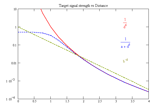
        The graph above shows three curves. The distance axis is not in any particular units. This scale would depend on the sizes of the coil and the target. The signal strength is plotted on a log scale.

        The red curve is 1/d^6. This curve goes to infinity as the target approaches the coil. Since the coil does not vaporize when we touch it to a coin we can be pretty sure that this is not what the signal does as the target gets real close.

        The blue curve is 1/(a + d^6). I think this is probably the best description of what the signal does. "a" would depend on the size of the coils and the size of the target. I do not know how to calculate "a" but it would increase when the coil size increases and would decrease when the target size increases. At large distances this curve matches the red curve.

        The brown curve is b^-d. This is what I use for estimating signal strength. It is not very accurate but it is easier to calculate in your head. For a 9 to 10 inch coil and coin sized targets, "b" works out to be about 2 when "d" is measured in inches. So for each additional inch of distance the signal strength falls of by about a factor of 2. "b" would have a different value for different sized coils or targets.

        Robert

        Comment


        • #5
          Re: IB Receive signal level vs distance


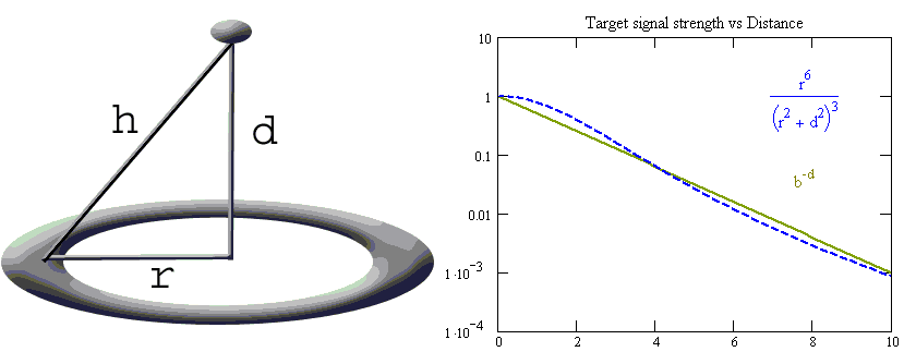
          I have a better function for signal vs distance. In the figure above "d" is the distance from the target to the center of the coil, "r" is the radius of the coil winding, and "h" is the distance from the target to the coil winding. If I assume that the signal is proportional to 1/(h^6) and then substitute (r^2 + d^2) for h^2 we get 1/(r^2 + d^2)^3.

          Of course real IB coils do not have a single r, there are separate transmit and receive r's and even those are not simple. But if I estimate my BM950 as having winding diameters of 4.5 and 8.5 inches and split the difference and call it an average of 6.5 which gives an r of 3.25, I get the blue curve above. The distance axis is now in inches. The r^6 in the numerator is just to normalize it so the value will be 1 at d=0. The other curve is the approximation I usually use, 2^-d.

          The nice thing about this formula is that it does not have any completely made up constants.

          To be more complete you would also have to take into account the radius of the target.

          Robert

          Comment

          Working...
          X