Announcement

Collapse
No announcement yet.

Uni-PI - Universal Pulse Induction Metal Detector board for microcontrollers like Ardiuno, PIC, AVR.

Collapse
X
 
  • Filter
  • Time
  • Show
Clear All
new posts

  • #46
    Originally posted by Tepco View Post
    I mentioned this circuit for GB, sorry for hand written quality but this is still on prototyping board. I guess I have to explain lot about, but in short: This is simple analog solution, can be easily added to almost any classic detector, but with MCU controlled timing can be even better. Instead of using two channels, here second sample subtraction is achieved using single integrator. Earlier I tried similar system using one integrator and GB adjustment achieved by varying preamp gain, but this was bipolar pulsing detector and differential 2 stage AC coupled amplifier, for classic detector this is out of question. Instead, I used integrator to produce subtraction. First sample closes S1 switch for 18uS (not quite critical, just convenient RC value) as in standard PI, integrator is connected via 10K resistor. After some delay, 15-20uS, another 18uS GB sample is generated, closing S3 and feeding signal to opposite integrator input, via 1.5K fixed resistor and 4k7 GB adjusting pot, so this ratio (10K\ 1.5K+adjustment) determine subtraction ratio. Also, this will screw up EF sample balance. To fix this, after 150uS inter sample delay, both S2 and S4 switches are closed to opposite ends of integrator, via same component values, compensating proportionally S1 and S3 contribution during first two samples. Integrator output will now be bipolar, going in one direction for short TC, in another for long TC, and remain fixed for certain TC, that of ground signal. Rest of circuit must be designed to accept this, in analog incarnation, full wave rectifier between SAT circuit and threshold circuit and VCO controlled from SAT output. This will produce high-low-high, or low-high-low tone for different objects. In case of MCU control, with signal digitized after SAT this is easy to be done in software. In this version timing is fixed and integrator gain changes, but gain can be held fixed and GB adjustment achieved by variable timing, more suitable for MCU design. Unlike two channel approach (requiring two channels to be as close as possible), here timing can be bit more “liberal”. Surprisingly, this appear to work just fine, at least on prototyping board, can be used to add GB to surf for example (in essence, just another 4093 is needed) but MCU control can be even better, nice platform for experiments.
    Did anybody make this GB circuit ? post #33, I have received an call for help by a member here who says the earth field elimination does not work with GB turned on, but when you turn GB off the EFE works ok.

    Comment


    • #47
      Hi 6666,

      I tried that circuit some time back, to get the EF to correctly cancel in GB mode I needed to add a 470ohm multiturn pot between the GB control and S2/S3. Then adjust the multiturn to get EF balance.


      EDIT I was also using a micro to make sure the pulse width was the same for all samples.

      Comment


      • #48
        Originally posted by mickstv View Post
        Hi 6666,

        I tried that circuit some time back, to get the EF to correctly cancel in GB mode I needed to add a 470ohm multiturn pot between the GB control and S2/S3. Then adjust the multiturn to get EF balance.


        EDIT I was also using a micro to make sure the pulse width was the same for all samples.

        Hi Mick thanks for the reply, its good to know the cct actually works with your mod, I will pass on the info

        Comment


        • #49
          Is integrator out noise level higher using method reply #33 vs increasing integrator GB sample time to ground balance?

          Comment


          • #50
            Originally posted by 6666 View Post
            Hi Mick thanks for the reply, its good to know the cct actually works with your mod, I will pass on the info
            No worries, 6666


            Originally posted by green View Post
            Is integrator out noise level higher using method reply #33 vs increasing integrator GB sample time to ground balance?

            Hi Green, yes method at post 33 does produce more noise, compared to using wide GB samples.

            The best method is still the 3 samples.

            3. First sample 5us, then variable delay in ns, then GB sample 130us and a 125us EF sample.

            Comment


            • #51
              Originally posted by mickstv View Post
              No worries, 6666


              Hi Green, yes method at post 33 does produce more noise, compared to using wide GB samples.

              The best method is still the 3 samples.

              3. First sample 5us, then variable delay in ns, then GB sample 130us and a 125us EF sample.
              Thanks. I've been using, 6usec delay, adjustable target sample(about 10.2usec), 4usec delay, 100usec GB sample. For EF, repeat sequence with target sample and GB sample controlling opposite switches to the integrator. Not sure if best timing, curious what your initial delay is. Your variable delay in ns, less than 1usec or ns resolution?

              Comment


              • #52
                Originally posted by green View Post
                Thanks. I've been using, 6usec delay, adjustable target sample(about 10.2usec), 4usec delay, 100usec GB sample. For EF, repeat sequence with target sample and GB sample controlling opposite switches to the integrator. Not sure if best timing, curious what your initial delay is. Your variable delay in ns, less than 1usec or ns resolution?

                Pretty sure the initial delay is about 7us, the delay between the end of the first sample and start of the GB sample is between 12 and 19us.

                The delay is in ns resolution. I use a micro to control everything, but the micro triggers a manual GB control circuit which feeds back into the micro to trigger the GB sample. If you want I'll find the micro schematic and post it.

                Comment


                • #53
                  Hello, 6666, mickstv, and green,

                  6666 thank for helping me

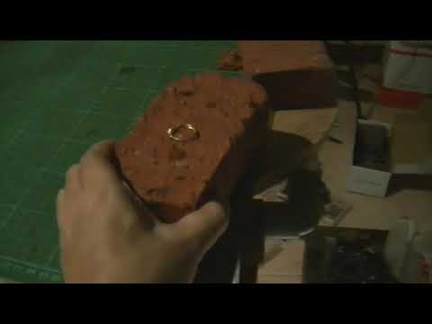
                  I have done for balance EF and GB , and can elimate redbrick, ferrite, and smooth tone treshold, no more flip flop tone
                  I use trimpot 100 ohm and adjust slowly for this
                  Click image for larger version

Name:	20170818_165417.jpg
Views:	1
Size:	403.6 KB
ID:	349171
                  For video i will upload to youtube,

                  Many thank for helping me, and i learn how to use GB
                  My timing
                  Delay 7us, first sample 20us, delay 10us, GB sample 20us, delay 150us variable to 200us for best result sensitive and emi, EF 20us
                  2000pps , pw 100us

                  Regards,
                  Wahyu

                  Comment


                  • #54
                    Hi Wahyu, I am very glad you got your project working.

                    What project is the printed circuit board for ?
                    is there any information about it ?
                    thanks

                    Comment


                    • #55
                      Hi 6666,

                      PCB project MIMITI_PRO , simple P.I with Ground Balance, schematic i combine from this forum,
                      for TX and timing i use TD3X, Preamp i use 2 stage preamp, integrator i use tepco and lowpass filter add, and for audio stage i use mickstv schematic, and Power supply +5v i use MPP

                      Video GB test
                      first GB off, and last GB on, sorry for chatter i test at home at night, test outdoor less chatter.

                      Comment


                      • #56
                        Originally posted by mickstv View Post
                        Pretty sure the initial delay is about 7us, the delay between the end of the first sample and start of the GB sample is between 12 and 19us.

                        The delay is in ns resolution. I use a micro to control everything, but the micro triggers a manual GB control circuit which feeds back into the micro to trigger the GB sample. If you want I'll find the micro schematic and post it.
                        Your ground decay seems to decay faster than mine. With your timings GB sample more than target ground sample. Maybe do to Tx time or delay between end of GB sample and EF sample. My Tx=160usec and delay between GB and EF about 600usec. Maybe something else.

                        Comment


                        • #57
                          @Wahyu

                          did you plan to pulblish sheme, pcb and code?

                          Comment


                          • #58
                            Hello bernte_one, please cek your pm

                            Thank

                            Comment


                            • #59
                              Originally posted by bernte_one View Post
                              @Wahyu

                              did you plan to pulblish sheme, pcb and code?
                              Hi Wahyu I would be interested to thanks.

                              Comment


                              • #60
                                Hi 6666, Done, Thank

                                Comment

                                Working...
                                X