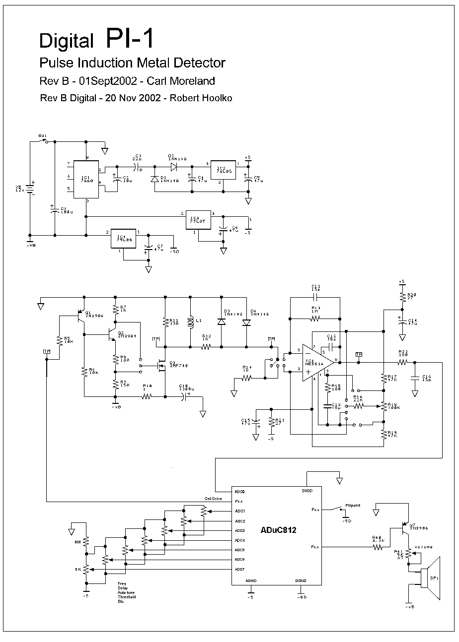
This is just an example to show what parts of the PI circuit could be replaced by a micro controller. I am not claiming that this design would actually work as drawn.
I just removed the parts of the original schematic whose functions could be performed by the ADuC812 microconverter, and left the rest alone. The ADuC812 is a single chip that contains an 8 channel A-D converter, 2 channel D-A converter, and an 8-bit microcontroller.
This is not the best way to connect the microconverter into the PI circuit, it was just the way that required the least amount of drawing. The + input of the amp would have to be biased so the output is within 2.5 volts of -5. The A-D input range is 0 to 2.5 volts above AGND which I connected to -5. Also the amplifier gain could be reduced.
I labeled a couple of the pins Px.x because I don't know yet which I/O pins would be best to use. Not all I/O pins are created equal.
I connected one of the analog inputs to the output of the amplifier and the other 7 inputs to pots to be used for adjustments like frequency, delay, auto tune, and threshold. This design does not have a digital display or control pad. It is all knobs and switches.
I show the analog output going directly to the speaker driver. But this chip might not be fast enough to do VCO, so the 555 might have to go back in. I have not tried doing VCO yet so I don't know.
Robert

Comment