Announcement

Collapse
No announcement yet.

Peak detection

Collapse
X
 
  • Filter
  • Time
  • Show
Clear All
new posts

  • Peak detection

    Hi,
    I am looking for a chip that works like a maximum peak detector.

    I want to receive 5 uSec wide pulses of variable amplitude.
    The time interval between pulses can vary between about 100mS and 5uS.

    I want to detect the max amplitude received during 1 mSec.
    In other words, I want a digital value for the maximum amplitude that was received in this 1 mS. (so 1000 values per second)
    The value may be a relative value, like with a ADC.
    A "max amplitude was xx% of a reference voltage" type of value

    The output may be parallel(preferred) or serial... as long as I can read 1000 values per second.
    8 bit output will be accurate enough.

    The amplitude will be maximum 2 Volt, however that can be amplified if neccesary.

    Does anyone know of a chip that does this ?


    Best regards Jan

  • #2
    Re: Peak detection

    See figure 20 in the link below.

    Or do a Google search for peak detector.

    Robert


    Peak Detector

    Comment


    • #3
      Re: Peak detection

      Hi Robert,

      Yes, this one was also the only one I could find.

      Suppose I have to do with this one, disadvantage is the +15 and -15 Volt it needs.
      (I have only 12V available...)

      Thanks anyway, Jan

      Comment


      • #4
        Re: Peak detection

        Jan

        It looks like it should be able to work from 12V if you can offset your signal so it is always between 4 and 8V. See graph TPC 8.

        Or after you have looked at that data sheet you could build your own from a dual opamp. If you are using an 8 bit ADC you do not need the accuracy of the PKD01.

        Robert

        Comment


        • #5
          Re: Peak detection

          Robert,

          How would I build one with a dual Opamp ?
          Remember there must be a "memory" in it because it must "remember" the highest amplitude that occured in the 1 msec window.

          The DAC I use will be in a PIC16F87x. (10 bits)
          The idea is to have 10 (0-9) steps of amplitude between 0-2 volt.
          So the output tells me in 0.2V steps how high the highest amplitude was.
          As you see, not really accurate.

          Best regards Jan.

          Comment


          • #6
            Re: Peak detection


            Jan

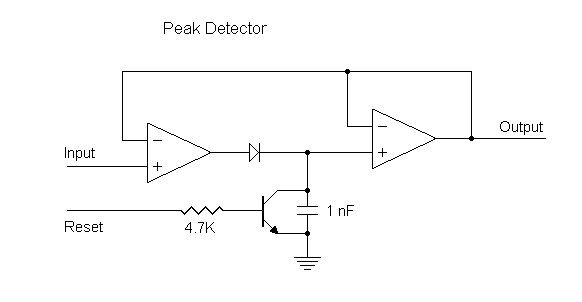
            This is the basic peak detector circuit.

            The first opamp provides a high impedance input so you don't load down your signal source, and a low impedance path to charge the capacitor.

            The diode is what detects the positive peaks.

            The capacitor is the memory.

            The transistor is to reset (clear) the memory. After you read the output with the ADC, pull the resistor high with a logic signal for a microsecond or so. That should be long enough to discharge the capacitor.

            The second opamp provides a high impedance load on the capacitor so it does not droop too fast, and provides a low impedance output.

            Robert

            Comment


            • #7
              Re: Peak detection

              Robert,

              Thanks.

              I will experiment with the Opamp's.
              Looks simple enough.

              Best regards, Jan

              Comment


              • #8
                Re: Peak detection

                A few points about this circuit.

                The diode should be a low-leakage type, e.g. 1N458A. There are ways of compensating for a higher leakage diode, but the circuit is more complex.

                The first opamp must be able to drive a capacitive load, have a high differential input voltage rating and a decent slew rate. The NE5534 is quite good here.

                The second amp should be a JFET or similar FET-input amp.

                The capacitor (in common with all sample/hold circuits) should be low-leakage and low-dielectric absorbtion, e.g. polystyrene etc. A small resistor in series with the capactor to give a time constant of about 1uS (in your case) would also help. e.g. 10nF & 100R.

                You should include a feedback resistor in the inverting input path of opamp 1. This protects the input of opamp 1 against discharge currents from the capacitor when power is switched off. You should also put an equal-valued resistor in series with the non-inverting input to maintain unity gain for opamp 1. e.g. 10K.

                You may also need a small (c. 30pF) capacitor between opamp 1 output and inverting input to adjust the settling time.

                For your application, you might also consider a high-value bleed resistor across the capacitor.


                HTH,

                Nicko

                Comment


                • #9
                  Re: Peak detection

                  Nicko

                  I admit that 1 nF may be cutting it a bit too close for a bipolar opamp. I wanted it small so it would be easier to charge, but maybe a little bigger would be better.

                  It seems to me that some of your suggestions are overkill for a circuit that has a 5 usec wide pulse and only needs 10% accuracy over 1 msec.

                  I was thinking of an LM124. I did not say that because I did not know if they still sell them. But I figured there must be something available today that is cheap and has a bias current less than 100 nA. I do not see that high speed is necessary. I would think that 1 MHz and 1V/usec would be fast enough.

                  Robert

                  Comment


                  • #10
                    Re: Peak detection

                    Hi Robert,

                    Yup - my comments were a bit of the purist type - with the changes I suggested you could get to less than 1% settling in 1uS. With an 8-bit ADC, Jan is looking at better than 1% resolution anyway, so going for sub-1% (actually about 0.1%) settling in 1uS didn't seem that far off.

                    If the pulse is 5uS long, you still have to detect possible changes during that interval - its not clear from the original post if the pulse is a square wave or a sample that many vary. So my comments were geared towards that - i.e. something that will detect changes intra-pulse, not just inter-pulse and will settle easily within the pulse width.

                    The components suggested are not very expensive - the 5534 will drive the cap nicely from 0-2V in the interval, and a TL081 or similar JFET is also cheap.

                    As the hold time is short - 1mS, you may indeed get away with a bipolar second amp and a small signal diode like a 1N914, however a JFET is not pricey and will definitely work.

                    BTW. I've been enjoying your comments on the DSP PI...

                    Nicko

                    Comment


                    • #11
                      Re: Peak detection

                      Hi,

                      The pulses are not really square.
                      Actually it is an echo received from a 200 kHz sonar pulse.

                      1 pulse per second... but many echo's from many different materials (rock, sand, seaweed etc)

                      I just want to see what happens if I plot the echo's on a computerscreen.
                      The amplitude of the echo is compared with a scale from 0-9
                      0=Low and 9=High amplitude.

                      I think I should see some sort of black/white picture of the seabed apearing on my screen.
                      Low tech .... but workable ...and affordable

                      Best regards, Jan

                      Comment


                      • #12
                        Re: Peak detection

                        Jan

                        If the received pulses are not square then Nicko is right that you would need a faster amp to accurately measure the peaks. However, now that you have given a more detailed description of the project, I don't think accuracy of the peak amplitude is very important. In fact it seems that using a peak measurement is arbitrary and you could have also chosen to use the average over 1 msec. So I would not worry too much about the speed.

                        I assume that the display will have a different x position for each pulse sent out and a different y position for each A-D sample, and the amplitude of each sample will set the intensity of that pixel. I do not think I would truncate the amplitude to 10 levels. I would just use the output from the A-D and add an offset (brightness) adjustment and a gain (contrast) adjustment.

                        I would think that you also need to adjust the amplitude according to the return time because echoes from farther away would be weaker, unless the hardware automatically makes that adjustment.

                        Robert

                        Comment


                        • #13
                          Re: Peak detection

                          Robert,

                          Each msec a new x position used.
                          The colors of the pixel depends on the amplitude of the echo.

                          The range 0-9 is used as example, it could be that I use a range 0-15 because I will use 2 transducers, each using 1/2 byte (=4 bits)to send amplitude data

                          The transducers are connected to a 50 meter signal cable.
                          I want to do the amplitude processing at the transducers and send the data serial to the PC.

                          In the design I use a variable gain amplifier (AD600) to step up amplification to compensate the loss of echo strength over distance.
                          Rate of amplification gain can be changed remotely with two sliders on the PC screen
                          (Step-up speed and step-up steps size) so I can experiment a bit.

                          The whole setup is very simple, but I hope I get a workable picture.
                          I am not looking for small objects like nuts and bolds but for something the size of oildrums.
                          So I do not need hightec stuff.

                          Later, when this thing works, I might have a look to see if I can get it more sofisticated.

                          Best regards, Jan

                          Comment


                          • #14
                            Re: Peak detection

                            Is this to do with a Metal Detector Jan?

                            If so I know EXACTLY what you're trying to do. I tried it and an 8 bit ADC is NOWHERE near accurate enough. You will need 14 MINIMUM.

                            Comment


                            • #15
                              Re: Peak detection

                              hehe.. no not a metal detector.
                              It is a lowcost, lowtech, Sidescan sonar.

                              best regards, Jan

                              Comment

                              Working...
                              X