Announcement

Collapse
No announcement yet.

State art GOLDSCAN IV

Collapse
X
 
  • Filter
  • Time
  • Show
Clear All
new posts

  • State art GOLDSCAN IV


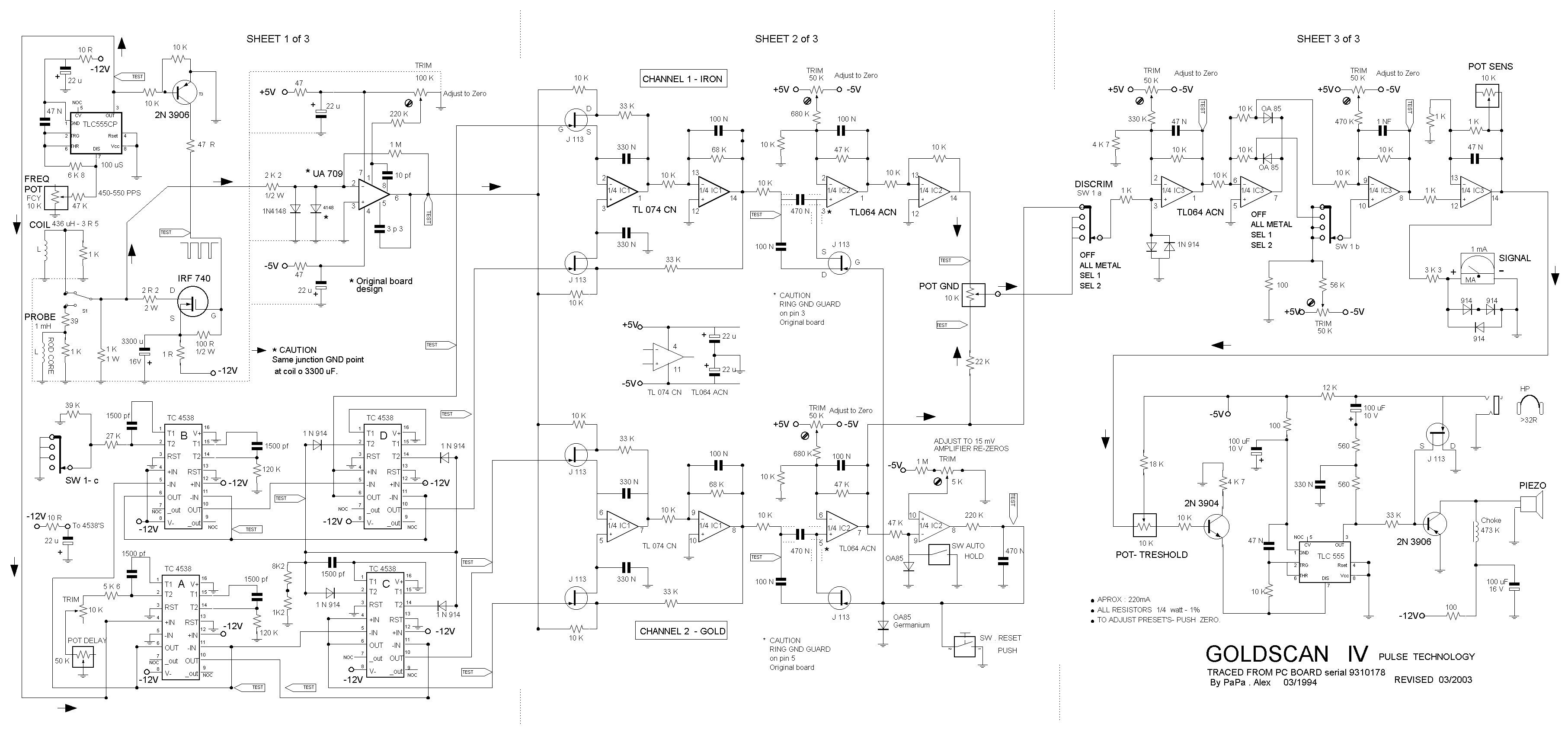
    Hello all the Forum,receive a very good schematic, old but for me state of art in analog Pi detector - just for now ,change the audio section to treshold audio (better than the tic tac and siren fire ) adjust at your taste the integrator time,change the pulse fcy up, paste a auto track switch......make a lot of experiments with this two channel PI at a great deep...
    The schematic is 100% ok , next time i send the power supply for this beast......
    Have fun my friends,

  • #2
    Re: State art GOLDSCAN IV

    Hi Alex,

    Thanks for sharing this with everyone. Very kind of you. I just barely looked this over but one obvious thing is the POT SENS appears to be shorted out and will not do anything as shown. My quick guess is it should be in parallel with the 1K feedback resistor but a 10K pot in parallel with a 1K resistor isn't going to be much fun either so don't know.

    JC

    Comment


    • #3
      Re: State art GOLDSCAN IV

      Hi Alex,

      it looks to me that the 1k and 10k poti suppose to be in series. And....the power supply circuit is also missing. Have you notice this?

      Chris

      Comment


      • #4
        Re: State art GOLDSCAN IV

        Thanks Jc for see this bug , yes you must cut the line in the schematic between center and right pole of the sensibility pot and is Ok ....sorry eveybody.
        In some days i post the alim circuit , a heavyduty good design , not the so lightness 7660 of the others sources...
        For the friends of the forum who ask me for the boards , sorry , you must make your own :
        www.expresspcb.com is a very good alternative and it is free.
        THE MOST IMPORTANT for the design of the BOARD , see the dashed line in the schematic from the ground of coil , ground of 3300, etc...all these gnd's must go to ONE junction point generally the 3300 capacitor GND.(see the caution in the schematic)
        Also , make you familiar GND is a positive path, not negative.....it is good to remember for the orientation of the capacitors....
        For the ua 709 ,remplace it with a 5534 ,work great but without capa 10pf and 3p3....
        For the Caution Ring guard it is not critical but better, ask to Carl who speak well English to explain to the forum what is it ....because with my por english i can't....
        Like I say it is a great PI detector , I make several version with improval treshold sound , highter frequency pulse ( change the 47N to 22N ),also a 6K8 and switch in parrallel to 6K8 to cut half the power consum etc....and it is very good for mineralised ground......
        In my version i work with a +6V and -6V , a little bit volt for the op's....
        Also see the 1 K of the coil it is the damping resistor with other 1 k in parrallel this is igual to 500 R .....you can adjust theses Resistors for your particular coil ; to cut the ringing (see the oscillo trace).....
        Have a nice work ,and i repeat always to Carl ,thank you very much for your technical site and for all the guys who participated, sharing ideas,schematics,etc........Alex.

        Comment


        • #5
          Re: State art GOLDSCAN IV

          Hi Alex

          thanks for the nice diagram. What is the voltage adjusted with 50K TRIM poti below SW1b? Also adjusted to zero?

          Regards
          Chris

          Comment


          • #6
            Re: State art GOLDSCAN IV

            Hi Chris,

            The 1 and 10k pot in series makes the most sense, very good. Alex said he was going to post the power supply later.

            JC

            Comment


            • #7
              Re: State art GOLDSCAN IV

              Surely the wiper must connect to ground?

              Comment


              • #8
                Re: State art GOLDSCAN IV

                Hi alan c,

                Guess the wiper goes to the resistor and one end of the pot goes to the output of the opamp.
                This gives a sens range of gain of 2 to gain of 12, and the pot acts pretty much as a linear sensitivity control. So the little piece of wire shorting the pot should be removed in the drawing which I think is what alex said also.

                JC

                Comment

                Working...
                X