 Tweet
Tweet
KT, you continue to look at the BBS/FBS
---
this pic line 'a' is OK for you? has BBS coil current another form?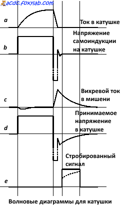
---
this pic line 'a' is OK for you? has BBS coil current another form?


 .
. 


Comment