
 Tweet
Tweet
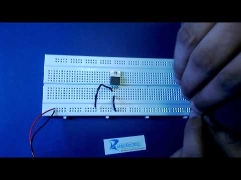
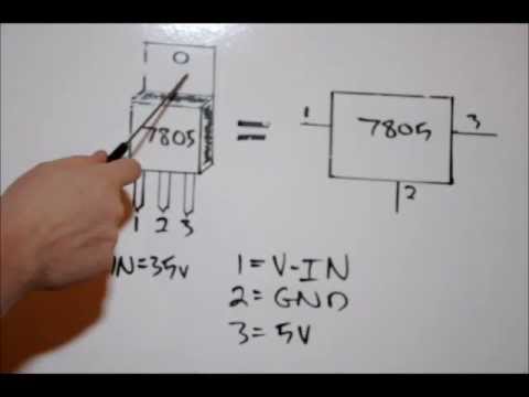
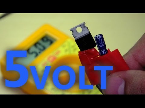
Have been working on building a Rev C Hammerhead and have struck problems with the +5v output on IC2. I have followed instructions up to IC6 and everything seems good (now that I replaced the ICL7660) except for the voltage at pin 7 on IC 6 and the output of IC2. I have gone through around 15 78L05's and none of them seem to be any good. Is this a valid way to check them? (see pic) The batteries are around 12v.
Thanks
Thanks


Comment