Announcement

Collapse
No announcement yet.

Bandido II schematic vs. Tesoro patent

Collapse
X
 
  • Filter
  • Time
  • Show
Clear All
new posts

  • Bandido II schematic vs. Tesoro patent


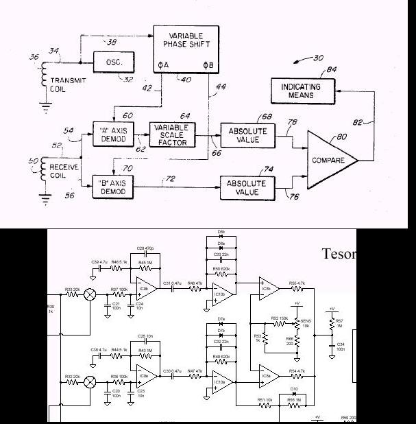
    How close is the posted Bandido schematic to what is described in the patent? I have been studying both, but I cannot see anything in the two sample branches in the Bandido schematic that has to do with absolute value going to the comparator.
    Is there maybe a different patent for the Badido, or am I missing something?

  • #2
    Re: Bandido II schematic vs. Tesoro patent

    Goodrat . It looks like you have the schematics of the Tresoro . Why don't you show that schematic instead of blocking out part of it ? Kees

    Comment


    • #3
      Re: Bandido II schematic

      Because it is already posted by Carl a few posts below.

      Comment


      • #4
        Re: Bandido II schematic

        Than why still block it ? We are having a hobby . That means that we are willing to exchange information . If we do not share , somebody may get the idea that we are in it for the money . That is surely not your idea is it ? Is it not fun to interchange info and make somebody else happy with some good information . That also he ( or she ) can build a good machine . That is what I call a hobby . Let's not be selfish and help our brother hobbyist to something good . This is just my idea ! Kees

        Comment


        • #5
          Re: Bandido II schematic

          Hold on!
          I was just asking a question about the circuit, and did not want to use up space by reposting what was posted earlier. Just look down a few posts to the Bandido threads. Carl posted a nice clean pdf file. Mine is a jpg of that same file.
          Anyway, it seems like there is no absolute value circuit as discussed in the patent whish is linked to on this site.

          Comment


          • #6
            Re: Bandido II schematic vs. Tesoro patent, plus NEW schematics page

            I believe the patent is for earlier Tesoros. I recall that single clamping diodes were used on the second-stage amps. Somewhere I have a schematic or two for the old "Deep Search" models, I'll try to dig 'em up.

            Kees (& all), I have finally got round to creating a "commercial schematics" page, kicking it off with none other than the B2uMax. I will try to quickly get more added, please be patient.

            - Carl

            Comment


            • #7
              So Carl, no more absolute value stage?

              It would then seem they deviated from their patent. Unless there was an update.

              Comment


              • #8
                Here's the question...

                You sample at two angles. You take these two values and feed to a comparator that compares to the sensitivity setting. If either is higher you get an indication. How are you eliminating the mineral influence?
                I thought I understood the explaination in the patent, but now with this Badido circuit, I am missing something.

                Comment


                • #9
                  Re: Here's the question...

                  Both have to be positive at the same time and greater than the sensitivity setting to get an audio response. This is an AND circuit. Also, the rc network tied to the comparator outputs is a small time delay so brief noise pulses are not heard.

                  The elimination of the mineral influence is done in the R channel (all metal channel) by using the ground balance control to initially minimize any ground influence and then uses the filters to further eliminate the ground signal. The X channel (the disc channel) relies only on the filtering action to minimize the ground effect.

                  If the signal is on both channels, then an audio response is generated.

                  Reg

                  Comment


                  • #10
                    Re: Here's the question...

                    But, if you are minimizing the gound influence on the R channel, what is left to send to the AND circuit? Why do you need both a voltage from the ground channel along with the X channel for a target response?

                    OK, they are sampled at different angles. Maybe if durring these two sample points (I believe they are about 90 degrees apart) if both levels are beyond the sensitivity reference then the target must be good and not a ground signal? Am I on the right track?

                    I was also looking at the all metal channel wondering what balancing really is doing in that mode. I concluded that this sets the ground channel exacly at 90 degrees (or 180?) from the xmit reference, and this calibrates the R and X channels for the disc mode to be a particular angle appart.
                    For a little schematic, it can really tax your brain.

                    Comment


                    • #11
                      Reg, about the AND circuit...


                      After running some simulations, there is a case where if R is less than the sense reference and X is high, the output is a high. What is the purpose of this condition?

                      Comment


                      • #12
                        Disregard the above logic!

                        Today my simulation IS like an and gate. I guess it is only different on Thursday's, or I made an error. Possibly selecting the wrong op amp to simulate.
                        The output is only high (not negative) when both are high.

                        Comment


                        • #13
                          Re: Here's the question...

                          The objective of the filters is to minimize the ground signals. The reason the R channel is also sent through filters is to further reduce any ground response and to keep the signals in sync with the X channel information.

                          The X filters have to be there to try to minimize the ground signals while allowing the target to pass through.

                          The R and X channel filters have to be built the same, or at least such that the signals basically stay in sync. This way, the signals, once they are at the comparators, will be in sync or timed the same. If they were not, then most likely, the circuit wouldn't work correctly.

                          Today, most VLF disctrimination circuits use two filter networks in series somewhat like those in the Tesoro. The earliest VLF discriminators used 4 high pass filters. One company, Compass used an extra simple high pass filter instead of just two filters for a little more ground signal reduction. Regardless if 2, 3, or 4 filters are used, the principle is the same.

                          Once again, the reason for the R channel going through filters is to keep the signals in sync. This R channel assures there is a target there when the X channel info is analyzed, so the response is only for a target.

                          Reg

                          Comment


                          • #14
                            Phase!

                            I percieve the situation like this:
                            The analog switches pass the recieve signal at 90 and some other angle for a period of 90 degrees. This sample is converted to DC by C20 and C21. The filter encountered next (IC9A and B) Are not filtering much AC rather slowly changing DC as the coil is moved. The next op amp (IC8A and B) Limit these swings to +/-0.7V and in effect compress the sensitivity. The comparator AND circuit gives an output if both are beyond the sense level pot. The only time this is true, is when the disc seting is at whatever phase shift for a certain target is required to mathimatically make this all work.
                            This is what I get from reading the patent.

                            Comment


                            • #15
                              Re: Phase!

                              The analog switches are basically doing the dc conversion. the caps you mention are just filtering noise.

                              You are right, the signal at the input of the first filter is basically a varying DC. The bandpass of the filters is something like 10 hz with a lower cutoff frequency of around 3 hz or so.

                              It has been a long time since I did the calculations on the above numbers so they may not be exact but close. Anyways, most ground signals fall in the 0 to 3 hz range while the harmonics of a target signal extend well into the desired bandpass.

                              The upper cutoff frequency is selected to minimize noise interference.

                              Now, as for the diodes across the second filter network, they are there because all that has to happen is the output voltage of this second filter stage has to exceed the threshold voltage set by the sensitivity control on the other input of the comparator. Any voltage above that just generates noise and problems. This technique of limiting the output of the second filter is quite common and doesn't effect the sensitivity at all.

                              The disc control adjusts the phase shift for when the sample or demodulation occurs with respect to the receive signal for the X channel. The ground adjust sets the phase for the R channel. Now, if the target phase is such that the resultant sample is of the proper polarity, then the final result will be an audio indication.

                              However, if the target phase response is not correct, there will be no audio output since the output of the demodulator will not be of the proper polarity.

                              As for the sampling time, I am not sure the duration on the Tesoro. It has been too long since I looked at the signals with a scope. However, the sample can be up to 180 degrees of the receive signal. Anything above that just subtracts in the result.

                              As for the phase of the sampling with respect to the receive signal, this is set by the disc control and is independent of the ground balance control. So, the phase angle can be something other than 90 degrees. In fact, it usually is.

                              Many manufactures just take two samples 90 degrees apart and then use a ratio of the outputs to obtain the same discrimination results. Tesoro does not do that with their circuitry.

                              One other little note, Tesoro uses the ground balance control to adjust both the phase of the sample AM channel and the R channel. However, they are offset very slightly by addition of a cap at the FET (a 10 pf on some prints). This little phase shift assures the hotrocks do not give false signals in the disc mode. So, when the ground balance is correct when listening to the AM signal, the R channel is offset just a little and is slightly postive. This cap cannot be eliminated but can be reduced in value a little make the R channel closer to the AM channel. In doing so, one will get a very slight increase in sensitivity but will also get false signals from some hotrocks such as magnetite.

                              Most manufacturers incorporated this feature of a slight offset to reduce complaints of false signals from rocks.

                              Reg

                              Comment

                              Working...
                              X