
 Tweet
Tweet
-
-
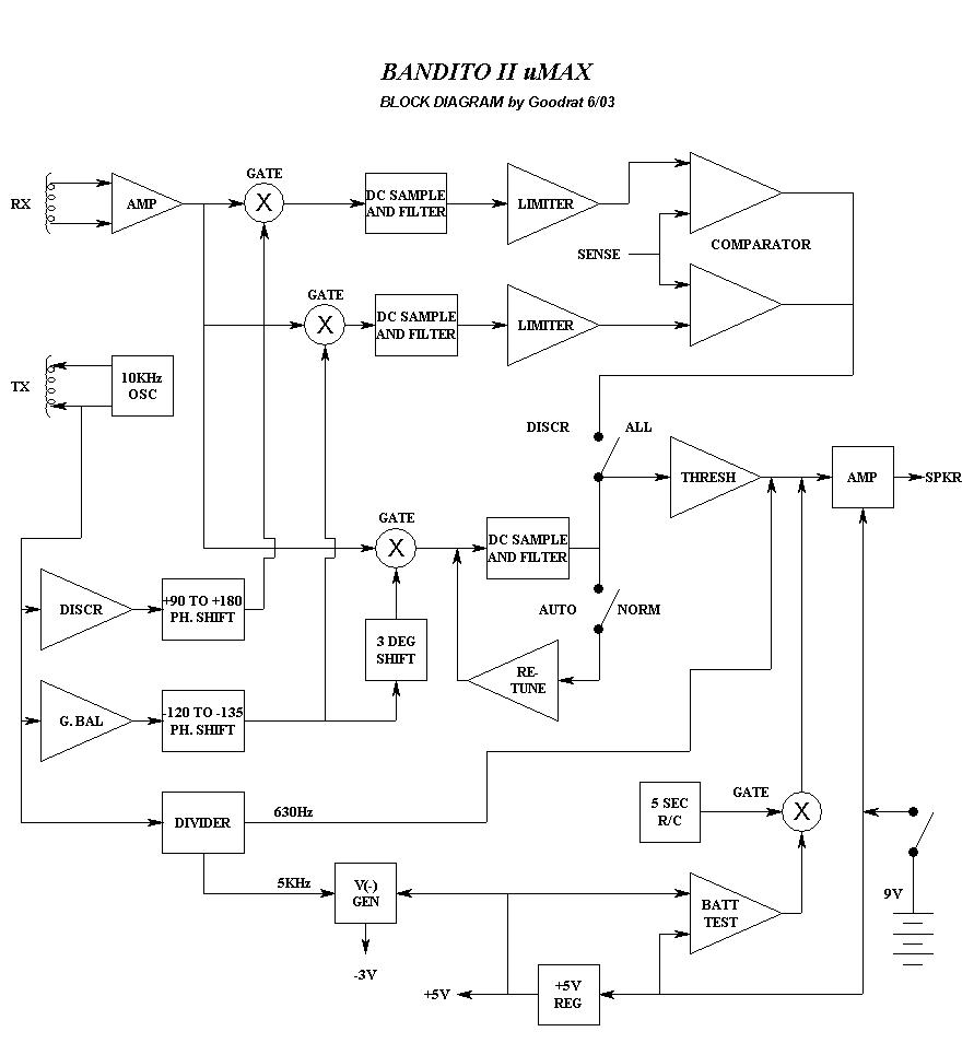
Re: Block diagram. Any corrections?
Looks right, 'cept maybe the divider frequencies. I think both are div-7, around 1.4kHz.
- Carl -
Re: Block diagram.
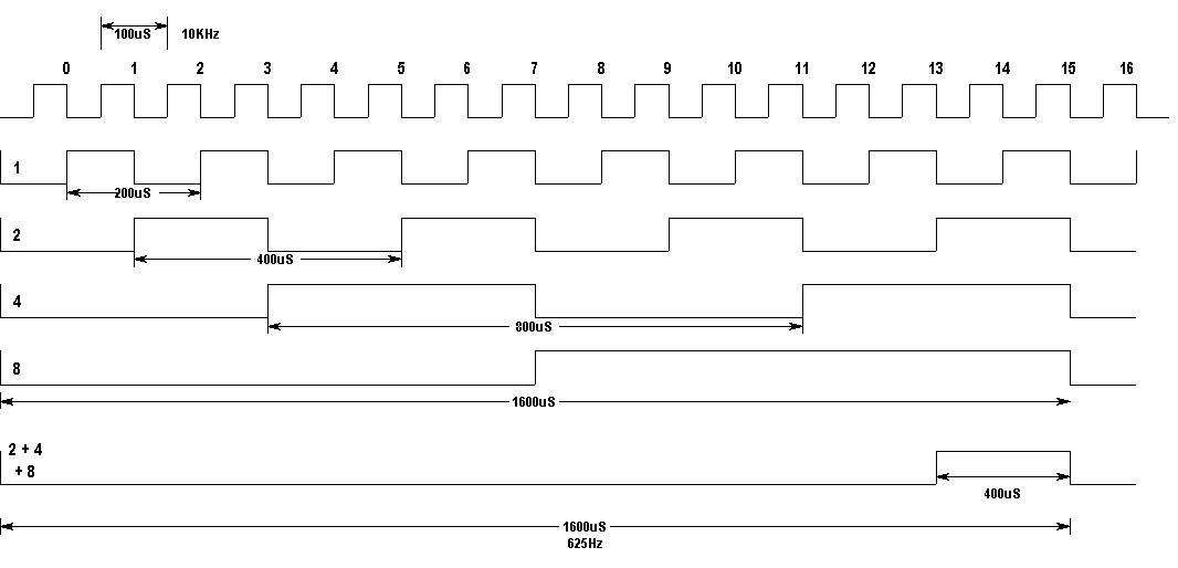
The Q1 output should be high every other positive cycle, and end up as div by 2 (5KHz).
The others or'ed with the diodes takes a little more thought, however the product spec reads 630Hz.Comment
-
Re: Block diagram.
Yup, you're right. I forgot that it's a binary divider. Q2-Q4 are diode ANDed, which creates a short duty cycle pulse. The frequency is equal to the lowest divide rate (fclk/16) and the pulse width is set by the highest divide rate. The middle diode is not even needed.
So for a 10kHz input, the audio f is 625Hz, with a 12.5% duty cycle. Tweaking the duty cycle like this, sets the "pleasantness" of the audio tone.
- CarlComment
-
I wondered about the diodes...
Yes, it must just sound better. What about the phase shifts going to the analog switches? The numbers are what the scope measured.
Anyway, here's a diagram for the signals at the binary counter.Comment
-
Re: Block diagram. Any corrections?
Hi Goodrat
I do same simulations in pspice about phase shifter circuit of bandido but i have a very different risults.
I have:
GB +60°,+90°
disc -10°,-110°
Are yours data misured on real circuit or came from simulation?
I'm not a spice guru so may be i do same errors.
Bye MaxComment
Comment