
 Tweet
Tweet
Okay, some of us know a mixture of factoids, facts, and urban legends. Examples: forward voltage is 0.6 volts, tempco is -2.0 mv/C, bandgap is 1.25 volts, emitter resistance is zero, and it's a square-law mixer. Knowing what it really does is for mathematicians and theoretical physicists who drink Boltzmann's Constant for coffee at breakfast, and the reason you went to college is so you could be reminded that all this stuff is over your head but you need the course credits for your transcript so pass the test and then get drunk and be glad it's over.
*********** OKAY, TIME TO CUTT THROUGH ALL THAT BULLSCHITT! **** Here's how the forward biased bipolar silicon semiconductor junction works.
Physicists dispute what the bandgap voltage of silicon is. I've seen everything from 1.19 to 1.25 volts. I'm going to say it's 1.20 volts for reasons you're about to understand. And what is a "bandgap"? That's for physicists to obsess over. As an electronic engineer, you don't need to know.
Get yourself a pencil and a piece of paper. Graph paper is best, but you can freehand this on blank paper and still "get it".
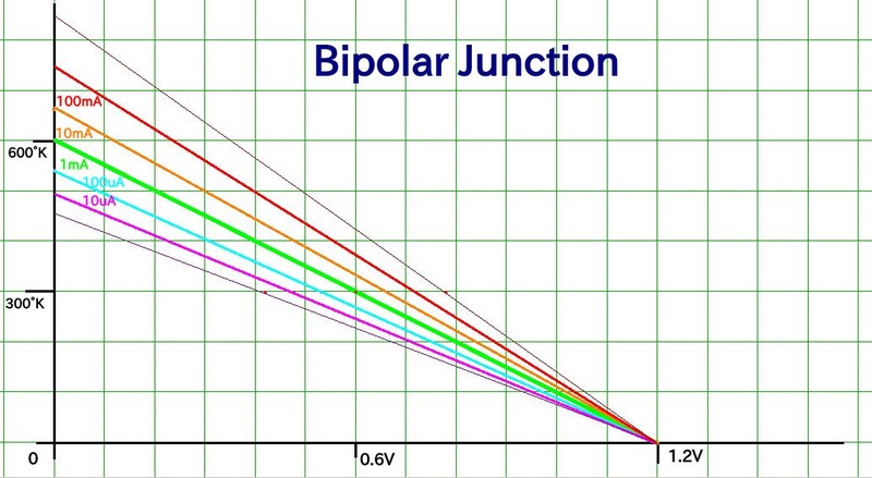
You're about to draw a graph in cartesian coordinates, northeast quadrant. The X axis is voltage. It goes from 0 to 1.2 volts. The Y axis is Kelvin temperature and it goes from 0 to 600 degrees.
Now draw a straight line from 1.2 volts and 0 Kelvin, to 0 volts and 600 Kelvin. That straight line represents current density. You don't know the literal density, but current is something you can measure and design a circuit around. For starters, call this current 1 milliampere, just to be able to call it something. If the bipolar junction is a small-signal transistor with the base connected to the collector operating as a "transdiode" voltage reference, the 1 mA value you assumed will probably be close to correct. But we'll get to "fudge factors" in a little bit. For now, that line is 1 milliampere.
Notice anything about that line? At room temp it's 0.6 volts. And its tempco is -2.0 mv/C. At 300K, its DC resistance is 600 ohms. At 600K, the voltage drop vanishes, thermal energy alone is sufficient to propel electrons across the junction energy barrier. DC resistance vanishes. You may not know what a bandgap is, but now you know something about what a bandgap does. The simplest of all possible graphs, and it told you that much.
What it didn't tell you is what happens at other current levels. Remember, the slope of the line is the voltage tempco.
Draw another straight line from the origin, through 540 mV at 300K, to the intercept at 545K. Tempco is 2.2 mv/C. That's 100 microamperes.
Draw yet another straight line form the origin, through 660 mv at 300K, to the intercept at 667 K. Tempco is 1.8 mV/C. That's 10 milliamperes.
We just discovered a new principle: the voltage difference caused by varying the current is proportional to the Kelvin temperature. What the graph doesn't tell you is that the magic number is 26 ohms AC impedance at 1 mA and 300K. So just take my word for it, until you've had the opportunity to verify it.
Every decade of current is another 60 millivolts at 300K.
*********** some oddball predictions, and are they true? ************
The base-collector "transdiode" exhibits diode law conformity better than a 2-terminal diode because of the amplification factor provided by transistor beta. Transistors vary in their ability to maintain log law conformance, but the good ones can achieve 6 decades of log law conformity. This principle is used in analog IC multipliers and precision log amps. The bipolar junction is one of the most predictable features you'll likely ever encounter.
The intercept at 0 kelvins is theoretical. Real world materials tend to go screwy as you approach 0 kelvins.
The Kelvin axis intercepts exist in the real world. If you get a semiconductor so hot that electrons can jump the NP barrier without being pushed by externally applied voltage, it's going to act like a short circuit.
Here's a factoid that may make all this fit into a pattern. Remember your crystal set with the galena crystal and the catswhisker you had to fiddle with? That's a Schottky junction, but it acts pretty much like a bipolar. Galena is the most sensitive because it has a really low bandgap. For this reason it's used in cooled thermal IR image sensing.
[more probably later.....]
*********** OKAY, TIME TO CUTT THROUGH ALL THAT BULLSCHITT! **** Here's how the forward biased bipolar silicon semiconductor junction works.
Physicists dispute what the bandgap voltage of silicon is. I've seen everything from 1.19 to 1.25 volts. I'm going to say it's 1.20 volts for reasons you're about to understand. And what is a "bandgap"? That's for physicists to obsess over. As an electronic engineer, you don't need to know.
Get yourself a pencil and a piece of paper. Graph paper is best, but you can freehand this on blank paper and still "get it".
You're about to draw a graph in cartesian coordinates, northeast quadrant. The X axis is voltage. It goes from 0 to 1.2 volts. The Y axis is Kelvin temperature and it goes from 0 to 600 degrees.
Now draw a straight line from 1.2 volts and 0 Kelvin, to 0 volts and 600 Kelvin. That straight line represents current density. You don't know the literal density, but current is something you can measure and design a circuit around. For starters, call this current 1 milliampere, just to be able to call it something. If the bipolar junction is a small-signal transistor with the base connected to the collector operating as a "transdiode" voltage reference, the 1 mA value you assumed will probably be close to correct. But we'll get to "fudge factors" in a little bit. For now, that line is 1 milliampere.
Notice anything about that line? At room temp it's 0.6 volts. And its tempco is -2.0 mv/C. At 300K, its DC resistance is 600 ohms. At 600K, the voltage drop vanishes, thermal energy alone is sufficient to propel electrons across the junction energy barrier. DC resistance vanishes. You may not know what a bandgap is, but now you know something about what a bandgap does. The simplest of all possible graphs, and it told you that much.
What it didn't tell you is what happens at other current levels. Remember, the slope of the line is the voltage tempco.
Draw another straight line from the origin, through 540 mV at 300K, to the intercept at 545K. Tempco is 2.2 mv/C. That's 100 microamperes.
Draw yet another straight line form the origin, through 660 mv at 300K, to the intercept at 667 K. Tempco is 1.8 mV/C. That's 10 milliamperes.
We just discovered a new principle: the voltage difference caused by varying the current is proportional to the Kelvin temperature. What the graph doesn't tell you is that the magic number is 26 ohms AC impedance at 1 mA and 300K. So just take my word for it, until you've had the opportunity to verify it.
Every decade of current is another 60 millivolts at 300K.
*********** some oddball predictions, and are they true? ************
The base-collector "transdiode" exhibits diode law conformity better than a 2-terminal diode because of the amplification factor provided by transistor beta. Transistors vary in their ability to maintain log law conformance, but the good ones can achieve 6 decades of log law conformity. This principle is used in analog IC multipliers and precision log amps. The bipolar junction is one of the most predictable features you'll likely ever encounter.
The intercept at 0 kelvins is theoretical. Real world materials tend to go screwy as you approach 0 kelvins.
The Kelvin axis intercepts exist in the real world. If you get a semiconductor so hot that electrons can jump the NP barrier without being pushed by externally applied voltage, it's going to act like a short circuit.
Here's a factoid that may make all this fit into a pattern. Remember your crystal set with the galena crystal and the catswhisker you had to fiddle with? That's a Schottky junction, but it acts pretty much like a bipolar. Galena is the most sensitive because it has a really low bandgap. For this reason it's used in cooled thermal IR image sensing.
[more probably later.....]
Comment