Carl would you know how to connect ( the quadruple op-amp LM 2902 ) in place of the CA 3035 by omitting one op-amp ? Cornelius
Announcement
Collapse
No announcement yet.
Carl / LM 2902
Collapse
X
-
Re: Carl / LM 2902
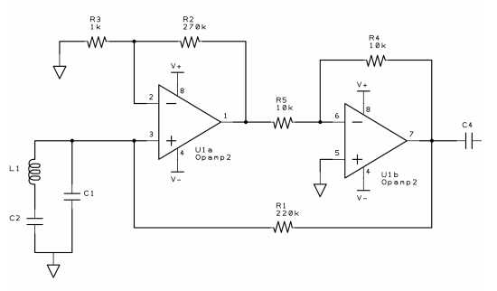
Here is a general opamp-based replacement circuit for the CA3035 circuitry. Two caveats — I have not built the CA3035 circuit, so this redesign is based on a hand-analysis of what the 3035 data sheet says; and, I have not built this circuit either!
I calculated the first amp in the CA3035 to have a gain of roughly 250, and the input & output are offset by about 1.5v above ground. The new circuit has no offset, so it must have bipolar supplies. The first opamp is set up for the gain and input impedance, the second for a simple inversion.
I suppose you could implement an offset and get rid of the neg supply, by replacing ground at R3 and pin 5 with the offset voltage. But R3 will need to be driven with a low-impedance voltage, which requires another opamp.
Build it, & lemme know if it works!
- Carl
Comment
-
what the !@#$ is goin' on...an 'ol ~324 quad but worse...dont bug the man...look at the data sheet.............this reminds me of a place when a "la-jit" 74xx had to be used - case the eng. usud the prop delay aspects therove...and u mst use a 7404....not ls,s,f,hct,act,thc.,lvhc....bs,...whatever...get off 'ol carls back---grab a "324 or "224 (it's better )...shove it....it'll work..if not "tweek" thge parisitic elements and be "done with it!!!!!"
r
Comment
-
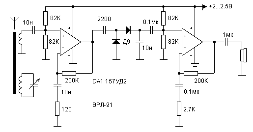
I think to find replacement to ca3035 we need to design an equivalent low frequency receiver circuit .
so let us divide the ca3035 receiver circuit to the following:
first the tuner which consist of two capacitors of 500 pf which are connected to ground,
then the tuner connected to the first stage amplifier in the ca3035 .
then com the detector circuit (demodulation) which consist of d2 c7(.1uf) and the r3 (25k variable) just to control the gain as I think.
now we have clear signal need to be amplified with the other two stages in ca3035
after that the amplified signal is connected to earphone .
please Carl tell if that is true because I am trying to make equivalent circuit with lm348
I need to know at what stage the detector circuit come after
and what gain we should make at each stage
I will post the circuit as soon as I finish it
Comment
-
Hisoka,
I have no idea about the RX loop voltage, I'm not even sure what you are trying to do. Once upon a time I posted an equivalent replacement for the CA3035, which was used in a metal detector circuit people were trying to build. I never built the detector, and never even tested my CA3035 equivalent, so I have no idea if any of it works. If you don't know electronics very well, then I would suggest you look for a different circuit to build.
- Carl
Comment
-
CA3035 is very oldest obsolete. you will find the datasheet attached.Originally posted by Hisoka View PostPlease Carl can you give me the offset voltage of ca3035 because I couldn't find it in the ca3035 datasheet
Comment


Comment