Announcement

Collapse
No announcement yet.

Help identify DIP 14 IC that drives meter

Collapse
X
 
  • Filter
  • Time
  • Show
Clear All
new posts

  • Help identify DIP 14 IC that drives meter


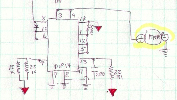
    This IC takes the received/amplified signal as an input on pin #8.

    It drives the meter in step with the increased audio in the XL 500 pulse detector.

    Would like to identify this IC. It dates from 1984.

    The red triangles are the positive battery (+8.4v) and the ground is the neg battery terminal.

  • #2
    Re: Help identify DIP 14 IC that drives meter

    4016 quad bilateral switch.

    Eric.

    Comment


    • #3
      Re: Help identify DIP 14 IC that drives meter 4016 ????

      Hi Eric,

      Are you sure? : Pin 8 is not a input control in the 4016 but a I/O switch of C. In the drawing , as i understand , the analog input of this circuit is pin 8 and the output for the meter is Pin 3 or 9. I recherched some circuit in a old databook and i found that the NE556 can correspond with input control and output .
      But it's not a standart use of this circuit...
      Sorry i can't help you more...
      Bye bye
      PhilippeM

      Comment


      • #4
        Re: Help identify DIP 14 IC that drives meter

        Thanks for your help with the IC number Eric. I had forgotten about the momentary switching to measure the battery voltage when first turned on. Clever design.

        Comment


        • #5
          Re: Help identify DIP 14 IC that drives meter 4016 ????

          Hi Phillipe,

          Definitely a 4016. The analog input goes in on pin 8 and is switched to pin 9 (meter input) by the timer control on pin 6. Pin 3 also goes to the meter input where pin 5 is also under timer control. Pin 4 goes to 2 x 22k resistors in parallel to give the correct meter scaling for battery voltage.

          Eric.

          Comment


          • #6
            Sorry Eric !!!


            Sorry i don't see for the first time the fonctionnality of this circuit.
            Here is a schematic:
            As i understand, when the circuit is power on the meter is connected to the power by the two resistor 22k and IC1C: that indicate a value of the batterie level . After the time out of R 22M and c 220 the output is connected to the input by IC1D.
            that's put me out is the diode D1 connected to control pin of IC1D: that's mean that the signal that will be send to the meter as to be at minimum higher than the input voltage control + voltage of the diode which is near 1.5 V + 0.6 V= 2.1V: Is that right?

            Thanks for your help and I apologize for this mistake.
            Bye Bye
            PhilippeM

            Comment


            • #7
              Re: Sorry Eric !!!

              Hi Phillipe,

              There are a few things that should be added to the schematic to make it clearer. Ground on the meter is in fact the -9V rail, as are the other grounds you have. Your V+ is the electronic ground. Input comes from the collector of a 2N3906 whose base is grounded. Emitter goes to a 3.3k resistor whose other end is to the output of the 741 dc amplifier. The dc amplifier has the threshold control which shifts the dc output positive. As it goes positive it turns on the 2N3906 and current passes to the meter. The transistor is acting as a common base level shifter. The control voltage on pin 6 is high (ground) so the diode clips any excess signal to prevent the meter pointer from a bashing.

              Most PI's that use an NPN power transistor or an N channel Mosfet, have the battery + to ground. The + end of the coil is then ground, which helps when referencing the receiver circuit.

              Eric.

              Comment


              • #8
                Re: Sorry Eric !!!


                so like this.
                PhilippeM

                Comment


                • #9
                  Re: Sorry Eric !!!

                  Hi Phillipe,

                  Almost right Pin 4 of the 741 goes to the -5V rail developed by a 79L05 regulator off the -9V. V+ on pin 7 is +5V of course.

                  Eric.

                  Comment

                  Working...
                  X