Announcement

Collapse
No announcement yet.

White's TR Series 2 mod project.

Collapse
X
 
  • Filter
  • Time
  • Show
Clear All
new posts

  • White's TR Series 2 mod project.


    Howdy folks! Just wanted to share a project that I have been working on for a few weeks. A redesign of the old White's TR Series 2. The original was difficult to set up for optimum performance, had a terrible thermal drift problem and no discrimination. The good features were automatic ground balance and decent depth for yards and parks. At any rate, it's a fun, cheap and simple detector and it works.
    The change I made is a simple filter system to eliminate drift and made tuning very easy.
    See the link below:
    https://youtu.be/2dF09YP3E4o

    The coils are easy to build - 3uH shielded -about 100 turns on a 5 3/8" form, center tapped at 50 turns, 30 AWG . It should run right around 12k Hz. I used a USB-2 cable for the coil below. It works like the original. You can build larger coils too for more depth and coverage.

    For setup ? Adjust the 10K pot on the MPS6522 emitter for a 3v PP sinewave in Pin 1 of the CD4024.
    Thanks to Smitty II for helping with the board layout. Any interest just PM me.
    Don


    Attached Files

  • #2
    Good project.

    Comment


    • #3
      Originally posted by dfbowers View Post


      3uH shielded

      Nice refreshing for good old design. Thanks to share with us.

      3uH or 3mH?

      Comment


      • #4
        I'm thinking 3mH, seems more reasonable.
        I recently tried to copy another ancient coinmaster 2D, but etching process went horribly wrong.
        If anyone's interested, I can post the layout file.

        Comment


        • #5
          Hello you both,

          pls show pcb layout, for whites tr and coinmaster
          or you prefer personal messages?

          Comment


          • #6
            There was a thread with some more photos of the board somewhere on forum. Here is the sprint layout along with schematic and photo. Should belong in other thread if I could only find it.
            Attached Files

            Comment


            • #7
              Good job friend. Congratulations. Your pcb files share please

              Comment


              • #8
                just a start, maybe ech of us can add some parts, my eyes falling asleep soon

                pcb.zip

                Comment


                • #9
                  Soo few components, worth to try... Any equivalent for the transistors and ic?
                  What about center tap coil, never built one before.

                  Comment


                  • #10
                    Originally posted by ripsdevala View Post

                    What about center tap coil, never built one before.
                    You should be somewhat precise in turns count, otherwise this no need to be a problem.

                    First you need to establish how much uH you get with your coil body (say 22cm in diameter) per single turn.

                    To get this you need first to wind about 20 (more are of course better) probe turns on your coil body.

                    Then you need to measure inductance of those 20 (or more) turns.

                    Say you got 300 uH per 20 turns, so inductance per single turn is (300/20) approximately 15uH.

                    According schematic we need coil with total 3000uH., so we need (3000/15) 200 turns in total.

                    Our center tap is at 100th turn.

                    Cu enameled wire of about 0.25mm in diameter will be acceptable.

                    Comment


                    • #11
                      By adding turns to a coil, you cannot simply multiply. It's not a linear relationship. I can tell you that 100T with a centertap on a 5 3/8" form will give you something close to 3mH.
                      Sometimes I take a turn or two off to get close to 12kHz. Also, if you are off a bit it probably won't matter that much. I built a few coils that were + or - 1000 Hz and it worked just fine.
                      About the centertap.. Just use a USB2 cable and use the shield lead wire to ground your centertap and coil shield.. Pretty simple.
                      Also. I can post up a complete parts list. Parts are readily available but I would not start substituting parts as some are critical.
                      For example.. The TL082 will not work in place of a TL072.. at least I could not get it to work. The MPS6522 is a high gain transistor and it's good to stick with it.
                      Same goes for the LM358. It has to work right at 0V and other op amps may not work at all. Other than that, its easy to build and use.
                      Don.

                      Comment


                      • #12
                        Originally posted by dfbowers View Post

                        By adding turns to a coil, you cannot simply multiply. It's not a linear relationship.

                        Don.
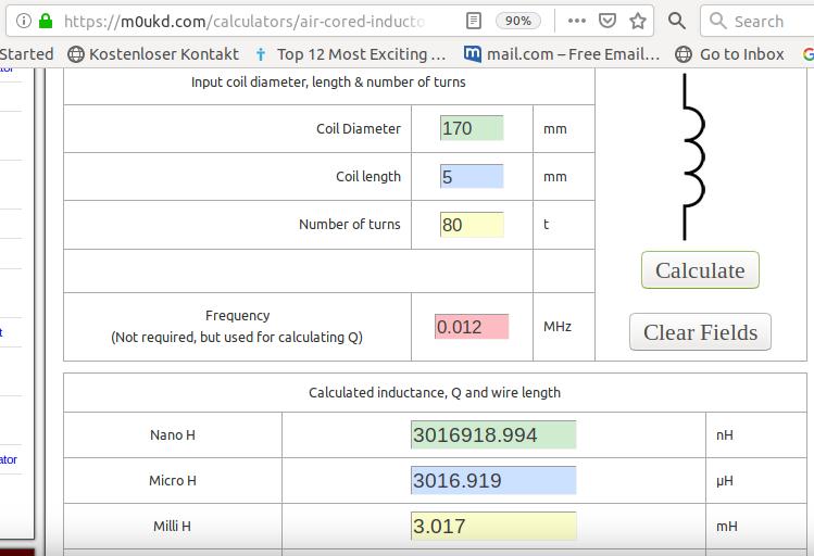
                        Agree. It is better to calculate it using some of online air core inductor calculator. par example:

                        https://m0ukd.com/calculators/air-co...or-calculator/

                        For 17cm coil body you get 80 turns for 3mH, so center taped at 40th turn:

                        Comment


                        • #13
                          Originally posted by dfbowers View Post

                          The MPS6522 is a high gain transistor and it's good to stick with it.

                          Don.
                          If MPS6522 is not available, we can try with such replacement:

                          https://www.el-component.com/bipolar...istors/mps6522

                          Comment


                          • #14
                            Originally posted by WM6 View Post
                            You should be somewhat precise in turns count, otherwise this no need to be a problem.

                            First you need to establish how much uH you get with your coil body (say 22cm in diameter) per single turn.

                            To get this you need first to wind about 20 (more are of course better) probe turns on your coil body.

                            Then you need to measure inductance of those 20 (or more) turns.

                            Say you got 300 uH per 20 turns, so inductance per single turn is (300/20) approximately 15uH.

                            According schematic we need coil with total 3000uH., so we need (3000/15) 200 turns in total.

                            Our center tap is at 100th turn.

                            Cu enameled wire of about 0.25mm in diameter will be acceptable.
                            Coil inductance goes up by the square of the turns difference. Double the coil turns the coil inductance is 4 times higher. Triple the turns and the inductance goes up by 9 times.

                            Here is a good little math trick for estimating the effect of coil turn increases on inductance. If 20 turns makes a 300 uH coil, then a 3000 uH coil needs the square root of 10 or 3.162 times 20 or about 63 or 64 turns.

                            Here is how to calculate single turn change effects on inductance. If 20 turns makes a 300 uH coil then 21 turns is only 5 percent higher. Do this: 1.05 times 1.05 is 1.1025 times higher or 330.75 uH.

                            Wire with thicker insulation separates the wire turns more and produces less inductance increase than my math theory indicates.

                            This should get you closer to your desired coil inductance.

                            Joseph J. Rogowski

                            Comment


                            • #15
                              Originally posted by bbsailor View Post

                              This should get you closer to your desired coil inductance.

                              Joseph J. Rogowski
                              Thank you for useful suggestion and calculating instruction.

                              In praxis I measure inductance in turns step (by 10 or by 20 turns par example)
                              by sand of small part of wire lacquer, measure L, an then paint lacquer protection
                              again by using nail lacquer.This way I get exact coil inductance.

                              But here we need center tapped coil, so it is probably better to use coil calculator.

                              Comment

                              Working...
                              X