Announcement

Collapse
No announcement yet.

New Metal Detector Genre - Full Circuit Diagram

Collapse
X
 
  • Filter
  • Time
  • Show
Clear All
new posts

  • New Metal Detector Genre - Full Circuit Diagram

    Friends,

    This concept has met with such popularity (in the last two days I have received e-mails from Poland, USA, Venezuela, England, Denmark, etc.) that I have designed an embodiment especially for the Tech Forum.

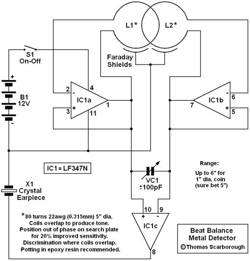
    You will see that there are two transmitters in the circuit, each comprising only an inductor (search coil) and an op-amp. The frequencies of the two transmitters are mixed through a third op-amp, and fed to a crystal earpiece (or piezo sounder - but then volume will be reduced).

    On the surface of it, this would seem to represent nothing more than a twinned BFO detector. However, mutual coupling adds the "balance" of IB, and boosts sensitivity way beyond that of BFO. VC1 is used to obtain a suitable beat frequency or heterodyne (say 200-300Hz).

    This is a very simple embodiment of the concept of course, and sensitivity could be boosted significantly beyond that shown with a slightly more complex design. In principle, all that is required is two identical transmitters, a coupling capacitor VC1, and a suitable mixer.

    I have dubbed the concept Beat Balance or BB, thus giving a nod to the two genres which underlie it.

    With kind regards,
    Thomas Scarborough.


  • #2
    Re: New Metal Detector Genre - Full Circuit Diagram

    When you say it Descriminate, What does it descriminate against?
    Just magnetic and Non-Magnetic?
    Or Different Metals?

    Comment


    • #3
      Plagiarism

      Friends,

      Esteban Cabrera kindly referred me to an Italian site which has a design in concept the same as mine. This comes about as follows.

      I have corresponded for years with Giorgio Obole in Italy, who arguably maintains the largest metal detector database in existence. I mailed him the first embodiment of my design. I had at that time submitted the design to EPE Technical Editor John Becker. EPE magazine subsequently decided to turn the design into a full constructional article, which then took on a different form, now scheduled for publication.

      The Italian design uses text (in Italian) which is lifted straight from my original, unseen EPE submission. It uses two Colpitts oscillators, and an op-amp mixer - all lifted from my original unpublished design. It also uses a method of tuning (RV1) that appeared in the unpublished EPE design, but which I subsequently considered inadequate. All of this I sent to Giorgio Obole in Italy, and I kept the receipt.

      I am a well known electronics author who has built a reputation for original design. As a matter of interest, I previously originated a minimalist IB design that stripped out the level detector and amplifier sections, reducing component count for a good IB detector to less than a dozen components. The concept was published in two magazines, and subsequently went into production as a kit with Dick Smith.

      I can't tell what role Giorgio has to play in this, because the Italian design is now published anonymously - but it is not difficult to show that my design has been "lifted", without acknowledgement. Over the years, several designs of mine have been plagiarised from magazines or websites, to appear under other names with other publishers. I am still completely baffled as to why anyone would want to do it. It's human nature, no doubt.

      With kind regards,
      Rev. Thomas Scarborough

      Comment


      • #4
        Postscript

        This story leads to Tech Forum correspondent Piotr in Italy, alias "Proscan". I have immediately lodged an appeal with the Italian Patent Office to stop an application, on the basis that there is abundant proof that my concept was placed in the public domain well before this.

        Thomas.

        Comment


        • #5
          Re: Postscript

          First, I would like you to answer my previous question.

          Second, as to your design: I have read all your arguements as to how your design differs from the patient #4196391 and I Disagree with your explainations of the differences.

          I have been through the Patient process a few times, Once while working for a company which was determined to get a patient as a "Status Symbol". As I was the "actual inventor" of this device, and I use this term loosly, I am the patient holder along with the guy who paid for the patient. What a Joke! Anyone can get a patient on anything, just depends on technicalities as to how you want to "Screw it Around".

          Reading al the info you have given, I believe your design is just a copy of that origional 1980 patient, with only minor changes.
          But by "no means" is it an "Origional Design".

          Seems to me that your the only one here making an arguement to justify your claim. Would be nice to see comments from the others involved.

          On the other hand, Who really cares.

          Just my point of view.

          Gary

          Comment


          • #6
            OK, let's cool down a bit...

            This forum is intended for the dissemination and discussion of detector technology. Everyone mentioned -- Thomas, Piotr, Gary, and Giorgio -- have all been contributors in this area, and I have had good dealings with them all. Let's not use the forum for finger pointing.

            I read through the Weber patent, and it is similar to Thomas' circuit, in that it uses a balanced coil. However, Weber gates the 2 oscillators, such that only one is on at a time. His only purpose, that I can gather, is to provide "spatial" information, i.e., whether the target is closer to coil 1 or coil 2.

            Thomas' circuit runs both coils simultaneously, and mixes the outputs of the two tanks with one another, instead of a reference signal as with Weber and most all other BFO designs. In a nutshell, Thomas has placed the reference oscillator coil in the search head, along with the main coil.

            Has this been "thought of" before? Possibly. I've "thought of" a number of cool circuit ideas, only to find out that others thought of them long before me. Years ago, I had even considered doing something somewhat similar to Thomas' design, but didn't bother, because I assumed that "pulling" between the two oscillators would lock them together, and kill sensitivity. Maybe I should build Thomas' circuit, and rethink my old idea.

            Unless you pore over all the patents, and have a good knowledge of prior art, it's pretty easy to assume that some circuit idea is new. I wouldn't get too worked up over this, especially when the information is being publically shared, for everyone's benefit. And I do appreciate everyone's contribution.

            - Carl

            Comment


            • #7
              OK, let's square up the facts

              Dear Gary,

              I quoted US patent 4,196,391 faithfully. The patent states that it seeks (quote) "least mutual coupling" and "least interaction" between the two inductors (see column 7, lines 12-13). Anyone can look at my design and see that it is heavily dependent on mutual coupling - not on excluding it.

              There are several other, significant differences, such as the eight building blocks of the patent. Anyone can look at my design and see that there are no eight building blocks there, or remotely near that. There is also the stated purpose of the designs, which is not remotely similar.

              But I don't need to repeat my case. There is a saying, "If it's different, it's different." My design is different, and that not a little.

              Your observations about patents surely have a lot of truth to them. At the same time, let us notice that you offer no substance to your claim that I have made "just a copy". I have given a good deal of substance myself, and it can be tested. You have not replied to the substance at all.

              I am a well known electronics writer and designer, with eight of my metal detectors having been published in many countries, in several languages, and two going into production. Five more of my metal detectors are pre-publication at this moment. I am well known for my originality, and none of my published designs has been challenged on this basis.

              I have received a message here from someone who is taking potshots without substance, under a pseudonym (and fails to spell "patent" correctly even once). You complain that I failed to answer your previous question, but your name does not appear previously. Are you referring to another pseudonym?

              Dare I say, we deserve better than this on a serious forum. This would not have seen the light of day on the EPE Chat Zone.

              With kind regards,
              Rev. Thomas Scarborough.

              Comment


              • #8
                Re: New Metal Detector Genre - Full Circuit Diagram

                Hi Thomas,

                I noticed that you position the coils out of phase. Could you please explain this by illustration. ie if both coils are wound in a clock wise direction and placed on top of one another and then moved to the overlap position. Would the coils remain same or would one be flipped over.

                Regards,

                Stefan

                Comment


                • #9
                  Thomas....Re: OK, let's square up the facts

                  Hi Thomas, Sorry about my misunderstanding!

                  When I looked at the two schematics, the first few stages look almost identical. As to patent write-ups, the way they do them, tends to confuse me, but the portion of it that I did read still seemed like both were very simular.

                  I will take your word on the differences.

                  However, Even if it was something that had been previously published, it's often difficult to know that, and honest mistakes can be made very easily.

                  Been there, done that myself.
                  And it was Never my intention to get you upset.

                  Life is too short for that stuff.

                  With reguards to the question I asked that you says, I never posted.

                  "The question is posted there"! It is: What does this circuit descriminate against? just magnetic/non-magnetic? or does it descriminate against actual metals?

                  As to "Patient or Patent", I Never claimed I could Spell and my typing is PICK and PECK, Slow and a real pain in the Butt!

                  Sincerely, Gary
                  Take care!

                  Comment


                  • #10
                    Re: Postscript

                    My reply. The link is below.

                    proscan


                    my reply

                    Comment

                    Working...
                    X