If this is your first visit, be sure to
check out the FAQ by clicking the
link above. You may have to register
before you can post: click the register link above to proceed. To start viewing messages,
select the forum that you want to visit from the selection below.
You?re going to look pretty silly for saying such things so confidently shortly. I?m not sure where the vitriol comes from in regard to Carl Moreland, but he?s plenty capable of developing this technology and bringing it to market. half-sine is not science fiction or a figment of anyone?s imagination. There?s every reason to believe this is exactly where the industry is headed. It sounds like Tom Dankowski in partnership with another company have already marketed a half-sine metal detector called the Tarsacci MDT-8000.
Harold, quite a number of people who have bought and used the Tarsacci are reporting it performs like nothing else. It was designed specifically for salt beach hunting so I don't know how widespread their praise is across other types of hunting conditions. See Tom Dankowski's forum for specifics.
KT, the Tarsacci has nothing to do with half-sine. Here is a post I made on DetectorProspector forum:
I've been reading through Dimitar's patent today. It uses a square wave (voltage) transmitter which produces a triangle wave current. When the coil is non-ideal (due to resistance) the triangle wave becomes slightly exponential, especially at lower frequencies. The patent describes an analog correction process after the preamp that compensates for this. Then it describes a the possibility of multiple demod stages (I/Q pairs), each with a preceding notch filter. One demod pair has a notch filter for ground, the others have different notches for different target responses. That's as far as I got, these things are tough to read. I fell asleep twice.
Bottom line is, the Tarsacci is 100% continuous-wave VLF. It is NOT sinusoidal like most single-frequency VLFs, but the demods are continuous-time just like SF-VLFs so it does not use time-domain demodulation like BBS/FBS. However, the preprocessing before the demods is done in time-domain fashion, so overall I would call it mixed time/frequency domain. I have to admit, I've not seen things done quite like this.
My own developments have included square-wave drive designs and I've considered coil compensation methods but at this point I've pushed it into DSP. But I understand exactly what Dimitar is doing there. The ground/target notching is more interesting to me and I think I know what he's doing but I need to keep reading.
Congratulations to Dimitar on a different and clever solution. Too bad FTP didn't hang on to him.
Hi Karl! Do you mean to such a signal when you say triangle wave current ?Otherwise the transmitter sends square wave signal and then I convert it to this signal. From the same transmitter I can convert the signal like this
Hi Karl! Do you mean to such a signal when you say [ATTACH]50897[/ATTACH] triangle wave current ?Otherwise the transmitter sends square wave signal and then I convert it to this signal. From the same transmitter I can convert the signal like this [ATTACH]50898[/ATTACH]
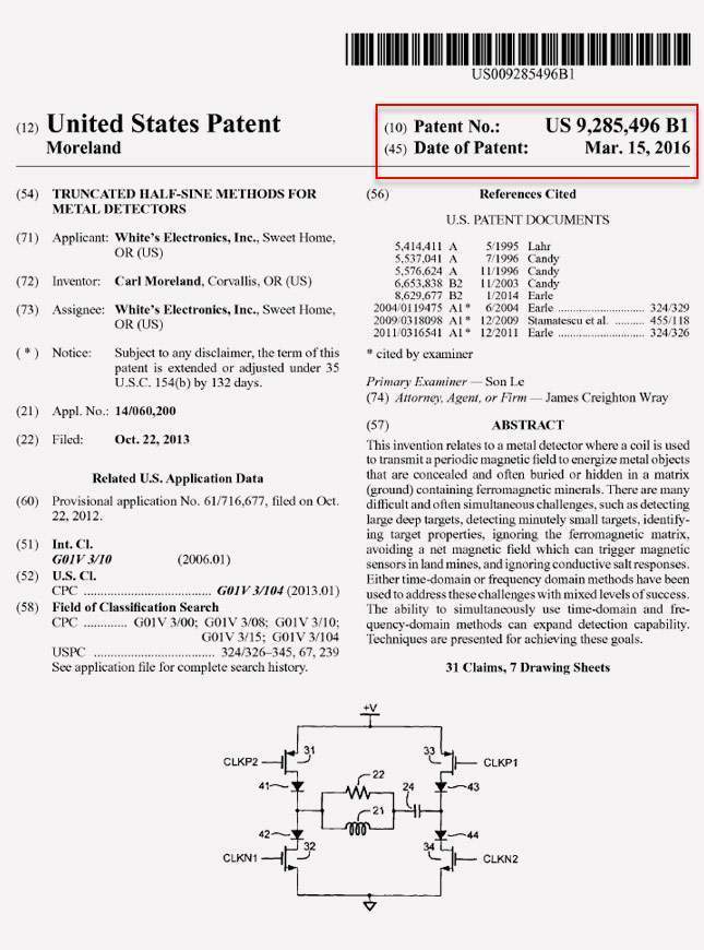
No, the coil is driven with a square wave and the resulting coil current is (ideally) a perfect triangle wave:
That's much better! And now I understand your previous plot, so it is also correct given the bad coupling.
The question is how these signals can possibly be advantageous since the exponential response is much weaker than a PI and the phase information seems to be lost.
This method is not PI, it is VLF. All the phase information is there, in the form of an exponential. You could use quadrature sampling a la VLF and extract a similar phase result directly from the exponential. But there are other things you can do via time-domain sampling that you cannot do with sinusoidal VLF that give it an advantage over sine-VLF. And you can easily change the frequency without worrying about changing a TX tank cap. Or even alternate between 2 or more frequencies.
A drawback of this approach is it is a wideband system and more susceptible to noise.
 Tweet
Tweet


Comment