If this is your first visit, be sure to
check out the FAQ by clicking the
link above. You may have to register
before you can post: click the register link above to proceed. To start viewing messages,
select the forum that you want to visit from the selection below.
Hi Olly, I just saw your post and connected the diode as described in your post and that fixed my board! I now have +5v on pin 15.
Thank you everyone for your help I appreciate it!
That's great news!
I've been trying in vain to duplicate the issue here, as it always works whatever I try. As I said previously, it must depend on the quality of the regulators. All the ones I have came from Farnell (Element 14). yatahaze323 - from where did you purchase your regulators?
And ... well done Olly for locating the source of this problem.
I purchased those regulators from Tayda electronics several years ago.
If these regulators are quite old stock, then it's possible they may exhibit the latch-up problem.
Anyway, we now have a solution. I have added this new information to the updates section here -> The Voodoo Project - Published October 2020
Can the solution of the diode solder on te regulator fix my problem ?
I will try it
Excellent video demonstrating the problem.
Since you can measure -12V on the cathode of D6 relative to the -12V supply line, this shows that the LT1054 ( U8 ) must be working correctly. Although you didn't confirm with an oscilloscope that U8 is being clocked correctly by the PIC, this must be the case otherwise the output would be zero. Also, if you measure between the cathode of D6 and TP1, this should measure as +12V. This is the voltage being input to U7 (78L05), which should result in an output from U7 of +5V. Clearly this is not a loading problem as the PCB is largely unpopulated. Therefore U7 must be going into a latch-up mode.
Solution: Put a reverse-biased diode ( 1N4148 ) across the output of U7. Probably the easiest place to do this is across C14. Diode must be soldered with anode connected to 0V and cathode to TP15.
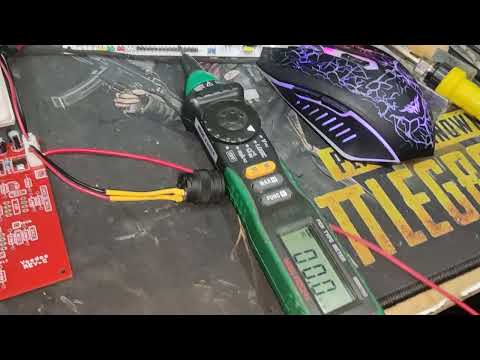
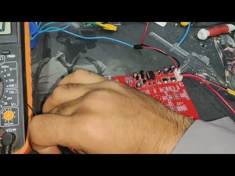
Here are a couple of photos which demonstrate that the power supply circuit does actually work. In this example there is no reverse-biased diode across U7, and the PCB is fully loaded.
Looking at your PCB in the video, it looks to me like C14 is inserted backwards. See attached PCB image.
The bottom line is that you must have +12V at the cathode of D6 relative to 0V, otherwise there will be no input to the regulator (U7).
If the capacitor is not the cause of the problem then perhaps the LT1054 is not being clocked by the PIC. You can check if the sync signal is present with an oscilloscope at pin7 on U8 (LT1054). If you don't have an oscilloscope, then a multimeter which can measure frequency will give a reading close to 1kHz.
Indeed the latest red PCB it seems as though C14 is reversed however in looking at the other video showing the stack of white PCBs I see C14 correctly installed on the top board.
Indeed the latest red PCB it seems as though C14 is reversed however in looking at the other video showing the stack of white PCBs I see C14 correctly installed on the top board.
I also noticed that, but there may be two faults which is making this difficult to debug.
It may be that the other boards require the diode, but the red board also has the capacitor reversed.
Actually, I'm starting to suspect that the LT1054 is not receiving a sync signal from the PIC.
I suspectes it was not original or fake (lt1054)
But i use an ic equivalent (lt1054) . (7660). And i get the same result . There is no tension (-12v) on the diode D6
I also noticed that, but there may be two faults which is making this difficult to debug.
It may be that the other boards require the diode, but the red board also has the capacitor reversed.
Actually, I'm starting to suspect that the LT1054 is not receiving a sync signal from the PIC.
Hello . Sorry fo the last video. I didn't notice the polarity of the capacitor c14 . But im sure the rest capacitors are in the right place in the other board.
I bouth all my component from aliexpress and ebay . 4 brand different. Also i try equivalent of the lt1054 like 7660 . But no change .
The signal doesn't reach to the ic from the pic , rather its stops at the resistence (R40) feeding the transistor 3906 .
So i have to buy an original ic (lt1054) . And try again .
Is there a seller you recommend me to buy original component from him .
Are you sure there's a sync pulse on pin 7 of the LT1054?
By the way, if you remove R37 and R48, the LT1054 will free-run using its internal oscillator. This should get the +5V supply working. Then measure the oscillator frequency. If it's a genuine LT1054 the frequency will be 25kHz, but if it's a 7660 masquerading as an LT1054 the frequency will be 10kHz.
 Tweet
Tweet


Comment