Announcement

Collapse
No announcement yet.

Delay times

Collapse
X
 
  • Filter
  • Time
  • Show
Clear All
new posts

  • Delay times

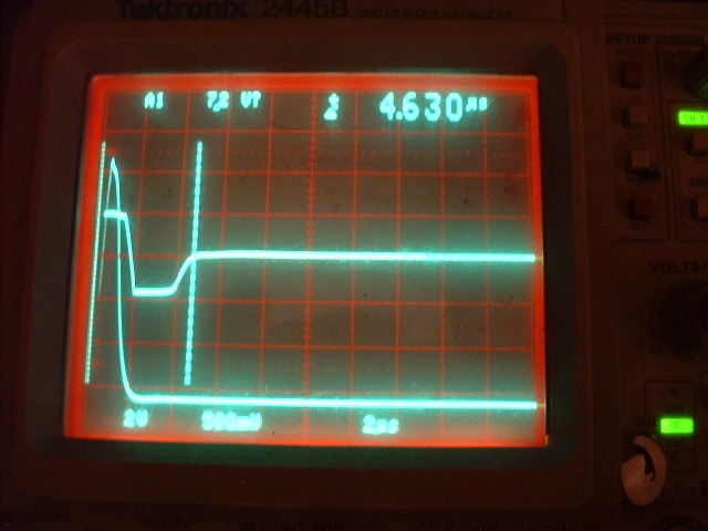
    Ok here comes my dumb question. I think we all get one or two questions like this. How do you measure delay time. Does it start at the turn off of the pulse to the fet and when do you consider the time to start taking a sample, is that the time the counter emf pulse reaches aprox zero? Do you want the counter emf pulse to have as short a width as possible, mine reads about 12 usec depending on the coil I use. Also what is considered overdamped and underdamped on the waveform. I use dave emery's concentric coil design and I do not want to over damp the tx coil or the rx coil.
    Thanks
    Ray

  • #2
    Re: Delay times


    Hi Ray,

    WOW, your few questions could be used to write a book since there is a lot of answers to the same question.

    OK,first, lets take your questions one at a time.
    1. How do you measure the delay time? ANS, I measure the time by using a dual trce scope with one probe on the damping resistor and the other on the output of the preamp. For me, it is the time from when the FET is turned off and the flyback signal starts until the sample is actually taken. On the HH this would be TP 2 and TP 4. If the sensitivity is up on the scope, you will be able to see when the sample starts and ends on the preamp output signal.

    Option 2. You could simply measure the time from TP 1 to TP 6. This will vary a little from the previous way because of the delays built in, but will be within a couple of usecs.

    2. "is that the time the counter emf pulse reaches aprox zero?" This would be the shortest delay time the could be used. A longer delay would have the sample taken after the receive signal has been at 0V for a while.

    3. "Do you want the counter emf pulse to have as short a width as possible?" This depends upon what what you are trying to do with the PI. If looking for small gold is the objective, then the answer would be yes. The shorter the time for the flyback pulse to decay, the sooner the sample can be taken, which results in better sensitivity to small gold.

    4. "what is considered overdamped and underdamped"? Again, it depends on the objective, so if searching for gold, then you want the damping to be as quick as possible. If you look at fig's 20 and 21 on the HH project, you will see the signal takes much longer in 21 to rise back to 0V. This signal, in my opinion is over damped. Actually, the signal in 20 is a little overdamped for my use, but not as bad as in 21.

    I have attached a pic of a decay operating at 5 usec or so. If I were to change the scopes's sweep settings to the same as on fig's 20 and 21 mentioned above, the signal at the output of the preamp would almost look like a square wave on my pic.

    Reg

    Comment


    • #3
      Re: Forgot to mention

      First, sorry the pic is a little too blurry and I forgot to mention a couple of things on my pic in my previous post. First, I should have moved the two channels over on the CRT just a little so measured decay time of 4.6 usec is a little short. It should be about a usec longer in reality. If you look, the sweep rate of my scope is 2 usec per div, so the pulse CEMF (flyback pulse) decays in less than 3 usec. This is quite fast, but is needed when trying to operate at very short delays.

      The pic displays the signals I get on one of my 11" DD coils. The two signals are, channel a with the probe on the damping resistor, and channel b on the output of the preamp.

      The 2 extra verticle dotted lines on the trace are the scope's built in measuring indicators. The distance or time between the two dotted lines is what is indicated in the upper right hand corner of the scope trace. In this case, the time between the two lines is 4.630 usec

      Reg

      Comment


      • #4
        Re: Forgot to mention

        Thanks Reg,
        I will take a look with my dual trace scope to see what they are. Yep you wrote a book but the pic is worth a thousand words.
        Thanks again
        Ray

        Comment


        • #5
          Re: Forgot to mention

          Reg,
          I think I have been trying to sample too soon with the main delay, looking at your pic I have been sampling on the slope before it rises to zero just before your last marker for time 2. It in fact gives me the best signal for gold. I adjusted the main delay componets so I could do this as I thought thats where I should be sampling. and yes the circuit is Carl's HH. Probably causes other problems I hadn't thought about.
          Ray

          Comment


          • #6
            Re: Forgot to mention

            Hi Ray,

            On my pic, I normally start my sample just at the point where the signal levels off at 0V. This is the point indicated by the second vertical line. This gives the most stable results, but not necessarily the loudest.

            It is possible to do what you are doing and take a sample with part of the sample on the upward curve as long as it doesn't cause saturation of the preamp or the next stage. In other words, the sample could start a little ways down the slope, but it will usually cause some strange things, and like you said, will generally produce the loudest signals.

            What will generally happen if the sample includes part of the slope is all signals normally will become much more erratic and intense, meaning the ground signal will be very intense and weak signals will generally be much louder. The final result is a PI that could be very unstable since the signals can change. The problem will increase as more of the slope is included in the sample window.

            By waiting until the signal levels off, everything is much more stable. The proper method is to get the decay curve to rise and level off very quickly so the sample will start when the signal has leveled off at 0V, if small gold is the objective.

            One other key point if small gold is the objective is to keep the sample time (sample width) short also. Once you have other things stabilized, you might want to experiment with different targets to see how the sample width affects the overall response. I have found that somewhere between 5 and 10 usec sample width is about right for my purposes. Anything less and it is possible to start to lose sensitivity. Anything longer and there is a sensitivity loss to very small gold and noise increases.

            If one is going to use the PI to look for iron artifacts or large iron objects only, then the sample can and probably should be taken much later if the area is trashy. If the delay is long enough, no shielding is required also. A long delay and long decay time will help eliminate signals from small pieces of junk.

            Reg

            Comment


            • #7
              Re: Forgot to mention

              One other thing if I may is that you have to consider the possible added decay from the ground. If you were to sample at 4usec in Reg's picture or down the slope towards the supply rail then you stand the chance of sampling part of the supply rail if mineralised ground lengthens the decay sufficiently. This can upset things quite a bit if the early sample is being mixed with a later subtract sample for some kind of math. This though depends on whether or not you use a high series resistance in the coil circuit combined with pulse lengths etc and also the ground you wish to search. I think it pays to have large samples of various ground for testing purposes even if you're only intending to use it on the beach.
              Rob.

              Comment


              • #8
                Re: Forgot to mention

                Hi Robby,
                Could you elaborate a bit on the series resistance and pulse length factor Please.
                I've been wondering how R-series/L affects the coils response to various targets.

                Thanks
                Kev.

                Comment


                • #9
                  Re: Forgot to mention

                  HI reg,
                  Can you give us more information about :
                  * some caracteristic of your coil 11'DD: number and diam of wire emeter, number and diam of wire receiver.
                  * the decay resistance value at emeter and at receiver.
                  * the direct voltage and the Lentz reverse voltage on the emeter.
                  Thanks for your help.
                  PhilippeM

                  Comment


                  • #10
                    Re: Forgot to mention

                    Hi Philippe,

                    The coil was one I made some time back so I am not sure of the exact measurements but the info I give will be very close. Unfortunately, I am constantly changing and trying things. Normally, I will write on the coil just what was done, but a lady friend's grandkids thought it was fun to peel off the tape I have on the coils. (They also adjust my scope when I am not home which is why the horizontal position was off a little on the previous pic).

                    The transmit and receive coil windings are almost identical. The inductance of both coils is about 335 uh. The diameter of both coils is about 8.7" and have 23 turns I think (they may have 24 turns). The main transmit damping resistance is 800 ohms. The receive damping I think is 1200 ohm, but not sure. The coil is sealed so I can't get inside again. The coil housing is a 11" Diameter round made by Bill Hayes. Here is the link, the part is A.

                    http://www.hayselectronics.com/parts.htm

                    Each coil I make works just a little different at the very short delays so I connect a small trim pot across the receive windings and adjust for the best curve. In some cases, I will change the xmit windings also and when I do that, I will also add a pot across the xmit so I can fine tune the adjustment on it also.

                    Once I get the best curve, I measure the resistance of the pot(s) and know the resistance needed. Then I replace the pot with a resistor.

                    The wire used for both the transmit and receive windings is served Litz wire I got from Nebraska Surplus Sales. The part number is (WHS) LW-12/36. This is equiv to a 25 AWG size wire and is made with 12 strands of 36 awg wire. Here is a link to the wire:
                    http://www.surplussales.com/Wire-Cable/LitzWire.html

                    I don't use any fancy winding technique but once the number of turns is wound, I glue, and lace the windings with thread to keep them snug. Once dry, I will add a layer of tape, then the spirawrap, and then the shielding. I will add another layer of plastic tape over the shielding to assure the two windings or their shields do not touch.

                    I use a Mogami dual coax S Video cable to connect the windings to the control unit. This wire has a very low capacitance of about 18 pf per foot.

                    My battery pack is a 10 pack of NiMh batteries so I have a little over 12V applied. The flyback voltage is a little over 100V.

                    The pic I posted was the signal I get on my GQ clone. I don't do quite as well with my HH but I come very close. I have the HH fully assembled and plan on shipping it shortly to a friend, so it isn't available for me to take pics of the actual waveforms on it.

                    One should be able to get the delay down close to 10 to 15 usec on their HH or other PI using a similar size coil. This is more than acceptable for any type of hunting. Being able to get a coil to operate at very short delays depends upon the FET used, damping, and other factors such as the coax used as well as the coil design.

                    On my HH I used a FET that has less capacitance than the 740 and the current is limited some because the FET does have a higher internal "on" resistance. This helps speed things up quite a bit as does the special S Video cable. Also, I use a couple of tricks I can't divulge because they were given to me in confidence by someone who manufactures metal detectors and sells them for a living. These tricks cut a couple of usec's off.

                    Reg

                    Comment


                    • #11
                      Re: Forgot to mention . Thanks a lot

                      Hi Reg,
                      Thanks a lot for your answer and your help.
                      I am very surprised by the lower flyback voltage : I use a basket coil of Diam 195mm ext , 34 turns of wire of 0,6mm
                      My decay resistor is about equivalent to 630 ohms and i use 1,5m of RG58 cable.
                      In this condition my decay curve give me near 15 /16µs: it's a bigger value than you ????
                      My flyback voltage grow up as 450V.
                      i'll try to do some new arrengement to try to reduce this delay.
                      I two day i'll be in hollydays , so i'll make this later.
                      Thanks again.

                      PhilippeM

                      Comment


                      • #12
                        Re: Forgot to mention . Thanks a lot

                        Hi Felippe,

                        You don't mention whether your coil is a mono coil or a DD. It is easier to get short delays on a DD or a concentric than a mono. I can't get the same decay curve with a mono coil with the same inductance as the one in the pic I posted.

                        Also, I am not sure just what your coil inductance is but I suspect it is about 650 to 700 uh. This will cause a much longer decay time.

                        It also sounds like you are using the 740 FET and have a higher current in the coil than I do. Both of these will slow things down a bit also. Some of the newer FET's have much lower capacitances which help.

                        The FET on the GQ clone is a different shape FET with low capacitance values both for the input and output. This helps quite a bit but the same FET can't easily be used on the HH because of design and current capability. The breakdown voltage is much less also which is why my flyback voltage is so low. The flyback voltage isn't the real issue. In theory, I would think a higher voltage would be faster.

                        I intentionally have my damping (decay) resistor at a higher value than I normally need, which will cause some coils to be under damped. This arrangement allows me to try a wider range of coils and obtain the fastest decay.

                        When I change the inductance of a coil and the coil is under damped and the decay needs to be "fine tuned", I add a second resistor of higher value across the coil windings either in the coil housing or in the coil plug, rather than change it at the pc board. This allows a very wide range of coils and a wide range of inductances to be used and tried without changing the detector at all.

                        Reg

                        Comment


                        • #13
                          Re: Forgot to mention

                          Hi Rob,

                          How are in the heck you? Hope all is well.

                          You are right, sampling down too far on the decay curve can cause problems, like you said, on many PI designs.

                          On the HH, they take a second sample much later and that sample is subtracted from the primary in the differential amp. If the two do not match, there will or can be some extra audio noise (usually a howl type audio) when the coil is swept from side to side through the air.

                          One can check the differential amp balance this way. By just raising the coil maybe waist high and moving the coil from side to side, one can tell if there is a proper balance to eliminate the earth field effects.

                          If there is a loud howl or audio output as the coil is moved, then it is quite possible that the sampling of the primary sample is too soon and part of the sample time is way down on the delay curve, thus upsetting the balance. A quick check is to turn the delay way up and then try raising and moving the coil again. If the noise goes away, then the first sample is probably too soon. If the noise doesn't go away, then further checks are needed to find out why.

                          One has to be careful and make sure the coax isn't moving and causing the audio when the coil is swept. This can give an indication much like the earth field effect problem.

                          Hope this makes sense.

                          Reg

                          Comment


                          • #14
                            Re: Forgot to mention

                            Hi Reg, hope all is well.
                            I’m ok and still endeavoring to persevere. Making something new from scratch is a nightmare (for me) but I’m slowly getting there. I reckon I’ve fallen for every trick in the book, plus some nobody’s even thought of, or maybe better put, most people wouldn't fall for.

                            Hi Kev,
                            This all comes back to a discussion we had on the PI classroom on whether or not we use resistance limiting or inductance limiting. I don't know the resistance of the coil in Carl's design but if a Minelab coil (around 0.4 ohms) was used then the decay would be affected more by ground minerals than if a high resistance coil was used or an in series resistor added. That is, the decay for the ML coil would then be more proportional to the pulse length whereas the decay would remain almost static regardless of pulse length if you use a high resistance coil circuit. There would be a point in between that could cause trouble if this wasn't taken into account.
                            I suggested obtaining samples of ground to check the effect on whether it would upset a sample taken too early, but it would also pay to grab a bag of magnetite (not just black sand) and look at the effect on the tx pulse. Some designs may be adding or subtracting this effect unknowingly as it can manifest itself in the supply rails depending on the method used and can be also added or subtracted depending on what you mix your sample with in between samples. For instance, the Micro PI mixes the sample with an average of the whole waveform. Ground and rocks that produce a large amplitude change when sampled after switch off have a much smaller effect on the tx pulse but all troublesome non-conductive ground is evident in the tx pulse to some degree. An 8" ML mono coil reads 332uH in air and around 362uH when introduced to a reasonably large quantity of magnetite and this is very evident in the tx pulse, especially in the later part. Coalmines use a lot of magnetite in their washing plants if you have one close by or find it hard to get elsewhere.
                            Rob.

                            Comment


                            • #15
                              Re: Forgot to mention . Thanks a lot

                              Hi REG,
                              I think that inductance is near 500/550 µh , it's a simple coil and i use a 740 FET.
                              As i said you yesterday , I'll test the DD coil during the next month.
                              Thanks .
                              PhilippeM

                              Comment

                              Working...
                              X