Announcement

Collapse
No announcement yet.

PI front-end PCB

Collapse
X
 
  • Filter
  • Time
  • Show
Clear All
new posts

  • PI front-end PCB


    One of the issues I've run into in experimenting with PI designs, is having to build & rebuild the same circuitry over & over. Another issue is that building this stuff on plug-in breadboards can degrade performance.

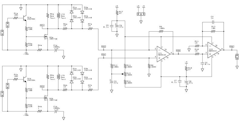
    So, I plan to build up some experimentation PCBs that will hold the front-end circuitry. Just the TX MOSFET, and the preamp(s). I have included 2 TX circuits, for a double-coil option, and a 2-stage preamp.

    Would anybody be interested in this? If so, I need to know how many boards to order. They will be single-sided through-hole, split ground planes.

    Any feedback, comments, ideas, etc are encouraged.

    - Carl

  • #2
    Re: PI front-end PCB

    Carl,

    Great Idea!

    Also, you could make it to accomodate a MOSFET socket so testing out various MOSFET coil drivers can be done easier. This is a great way to fine tune and adjust the critical components to optimize as far as you want to go without tearing up the standard circuit board.

    This concept may also be useful for eventually doing digital processing of the signals.

    Sign me up for three boards.

    bbsailor

    Comment


    • #3
      Re: PI front-end PCB

      Great Idea Carl.
      Let me know when and how much for 1 board.Your other board was excellent. If you use the same hole spacing for the coil cable and the +- power then it will work fine for me.
      Ray(NM)

      Comment


      • #4
        Re: PI front-end PCB

        Hi Carl. It's a good idea. Now my comments.
        1) I think that is better the power suply to be near the preamplifiers so maybe to put it in this board.It is not good idea to build the power suply every time on the breadboard.
        2)I don't Know if you try it but i think that is good to put a 4066 between the first and second preamplifier.
        Please let us Know about the final shematic afer the comments of the other guys so to see if the board is ok for us.
        I believe that the board is for standard components (no for SMD please answer for it).
        Geo

        Comment


        • #5
          Re: PI front-end PCB

          Sounds like a plan to me!!!! Put me down for two. Also I like BBSAILOR's idea of the MOSFET socket so that experimenting with MOSFET with different characteristics could be tested more easily!

          HH

          Beachcomber

          Comment


          • #6
            Re: PI front-end PCB

            Hello Carl,im interested Also. would be nice to see a dual board PI setup, that would be an equivelant to a pic-chip that has adjustable timing pulse,width,delay... etc but without the pre-program junk , but be just as powerfull, i know you can do it. Thank-you Gene L.

            Comment


            • #7
              Re: PI front-end PCB

              Put me down for one also please. Hammerhead board helped a great deal over breadboards with experimenting. Still have one problem though which is too much interference in the house even with the TV off. Anyone have any ideas how to reduce this problem?

              Comment


              • #8
                Re: PI front-end PCB

                Hi Carl,
                I would be interested in 4 boards, thanks.
                Just a thought. If you have a clear ground plane area down each side of the board say, 4mm wide, it would allow the assembly slide into an aluminium extrusion which would help with shielding the circuit from some interference.
                There are various comercially available sizes available at reasonable prices. Xtech is one in the US and I am sure other countries have similar manufacturers. I realise it all depends on board size but perhaps it could be made to fit a commonly available box, just a thought....

                Regards

                Brian

                Comment


                • #9
                  Re: PI front-end PCB

                  Great Idea CArl! I was thinking around the same lines. However for me to be interested I would like to replace all that 555 timer junk with a 8 pin PIC microcontroller. I replaced all that on a test board and it worked great.

                  I can provide pinouts for power and etc for the PIC. I used a PIC675. It was a little weak to drive the mosfet directly so put a low power mosfet between PIC and high power mosfet.

                  Also, I would not care for SMDs. Shielding someone mentioned and that would help but that is a black art in itself and you would have to come up with that. Maybe Eric could help.

                  I'd even send you a programmed PIC for testing if you supplied the timing signals AND I'd program the PICs for anyone that wanted if they'd pay a little extra over basic PIC plus shipping which wouldn't amount to much.

                  Comment


                  • #10
                    Re: PI front-end PCB

                    Carl, Keep us posted on your New PI Boards !! Im interested in 3 again . I got boards from you a year ago , they were great. Its just getting IC chips and parts is difficult here cause the distributor is crummy.Anyway looking forward to hearing your Latest news on the PI front-end board,and more. Take care Gene L. This forum is still #1 Thank-You

                    Comment


                    • #11
                      If you live in the states......

                      there are several places you can order your IC's and other parts that will ship directly to you home or office.

                      HH

                      Beachcomber

                      Comment


                      • #12
                        Re: PI front-end PCB - Replies

                        MOSFET socket: What does a TO220 socket look like? Don't think I've ever seen one. I use pin sockets on R's & C's when I want to swap them, but the pin sockets I have are not big enough for TO220 leads. Also, I'm a little leary of socketing the FET, as a poor contact can cause problems.

                        IO buses: I had intended to use 200-mil screw terminals for the coil, and 100-mil pins for the other I/O.

                        Power supply: I am keeping it off-board, because I can use the same power supply for multiple projects. No need to build the same supply circuitry for each front-end. A small, dedicated supply PCB would be another possibility.

                        Samplers: I wanted to experiment with a 2-stage preamp, so the sampling switched will come after the second preamp, and be on a seperate board. A PCB for the samplers & integrators is, again, another potential addition to a modular system.

                        Aluminum housing: The PCB will probably be smaller than any common housing size. I will include corner holes, so you can add extension wings if you like, and make it fit anything.

                        PIC vs 555: This PCB will only have the analog front-end circuitry. It can be driven by any digital method, including PIC. Personally, I will be using a PIC, and already have one coded to use a single rotary encoder for adjusting all parameters. This will be the basis for Hammerhead II.

                        -------
                        I'll try to get a first cut on the PCB posted in a day or two...

                        - Carl

                        Comment


                        • #13
                          Re: PI front-end PCB

                          Sounds good to me. I have been interested in using a pic but just have not pursued it yet.
                          When and If let us know.
                          Ray(NM)

                          Comment


                          • #14
                            Re: PI front-end PCB - Replies

                            Sounds great! I am glad you are going to use a PIC. They have sure simplified the control signals for me. The PICs I am using you could also use to control the switching for the pream and integrators which is what I am doing with the PIC675.

                            Comment


                            • #15
                              Experimenters Tip

                              Carl, and all

                              I make three pin MOSFET sockets by using the cheap Radio Shack 8 Pin IC sockets and cutting one pin off (slicing through the plastic) and slicing the plastic socket in half. The spacing is right and MOSFET 220 style devices fit into the IC pins. This will not work on the round pin type IC sockets.

                              This trick makes changing MOSFETS very simple. Just make sure that you mount the socket snug against the circuit board so you don't push the copper solder pads away from the board when you press the MOSFET in. Look in your junk box and try it out on a cheap style IC socket.

                              bbsailor

                              Comment

                              Working...
                              X