Announcement

Collapse
No announcement yet.

How metal detector work?

Collapse
X
 
  • Filter
  • Time
  • Show
Clear All
new posts

  • How metal detector work?

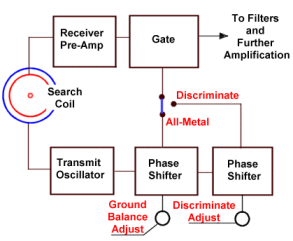
    I would like ask to anyone about this block diagram. Why the transmitter signal must be shift forrword/back the phase and compare it with the receiver signal. What the function the gate?
    Please explain it?


  • #2
    Re: How VLF metal detector work?

    Hi Erwin,
    I was reading a lot of scientific explanations about that, but never was satisfied, simple because they haven’t practical level for amateur understanding. So, I shell try to help you, from practical point of view.
    First, you have some delay of sinusoidal signal from Tx to Rx.
    On my understanding, Vlf detector is some kind of conductivity meter, and any substance near by balanced coil will provoke phase shift (less or more) in Rx coil, depending on they conductivity.
    Your diagram is valid only for analog Vlf detecting system, because in true digital detecting system, information can extract from numerical calculations.
    So, in analog MD Vlf system, you have two tasks:
    First – to avoid minerals in ground (G.E.B)
    Second – decrease or increase response from target metal (DISC)
    Because OP amplifiers are not smart like microprocessor system, you must find some easy way to make differences from different target response. Also, you must convert AC sinusoidal signal to DC.
    So, long time ago, peoples are get idea to make some kind of window, which can see only part of sinusoidal signal, and which can move in time. With such window (chopper), after low pass filter, you are getting dc signal, which level depending on target conductivity.
    Why phase shift?
    Easy way to make different response, from different targets, is to make some null DC level, from which you can analyze targets like negative (DC-decrease) or positive (DC-increase), or of course, zero response. You can do it with you block diagram.
    Any good analog Vlf detector must have a two such system, first for G.E.B, and second for Disc.
    Maybe I help a little?
    Jackdetect.

    Comment


    • #3
      how diagram for digital VLF detector?

      for VLF

      Digital:

      -Analog standard + VDI (DIGTAL)
      -OSC (LC) + frecuencimetre (Yuri)
      -XLT pseudo analog

      Only two system?

      Comment


      • #4
        Re: how diagram for digital VLF detector?

        Sorry,
        I am very limited in understanding such hi-tech units. Only was seen how they work on the field, and believe my, two system with analog buttons are working quite well.

        Comment


        • #5
          Re: How metal detector work?

          The "gate" can be a mixer, or a sampling switch. When the "gating" signal is the same frequency as the receive signal, this is called synchronous sampling, and is the basis for pretty much all of the VLF-type detectors.

          For ground balance, you would adjust the gate phase so that you sample the zero-crossings of the received ground signal. Therefore, the sampled ground signal would be zero, and everything else positive. For disc, you could adjust the phase even further, so that only high conductivity targets give a positive response, and everything else negative.

          - Carl

          Comment


          • #6
            Re: How are the Metal Detector PCB Boards Doing ??

            Carl, Any news or up-dates on the board you were working on " Hammerhead Front-End" ??? I Hope it is a 2 board when your done. That way it has a little room for expansion and or sockets for adjustments on sample, pulse width, delay , etc.. plus room for a pic chip. Keep us posted, I will buy 3 sets. Thank-you Gene L.

            Comment

            Working...
            X