
 Tweet
Tweet
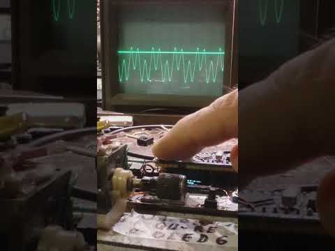
right? = wrong, valuable is info how much energy is coming out of Tx coil not how much you put to it, that depends to quality of the coil.
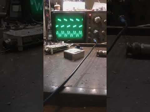
you can't directly compare 10kHz & 15kHz TX fields. To do that you need a current-mode probe = not sure about that ?
you can't directly compare 10kHz & 15kHz TX fields. To do that you need a current-mode probe = not sure about that ?
Comment